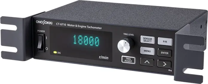
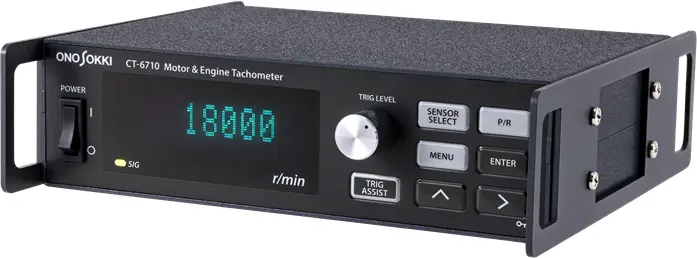
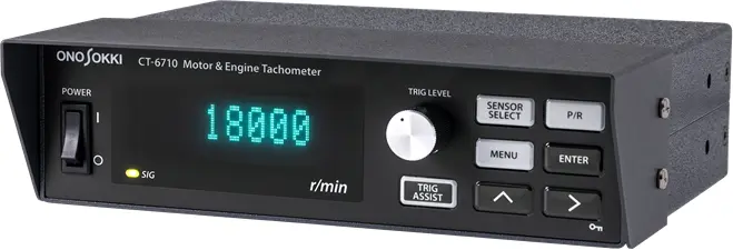
Motor & Engine Tachometer
CT-6710
Supporting a wide variety of sensors
Enabling various rotation speed measurement
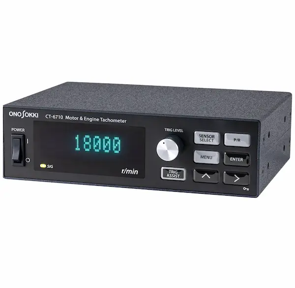

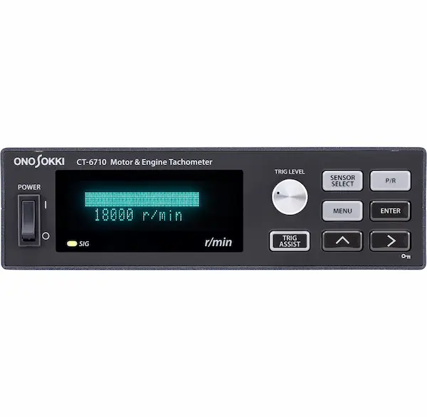
The CT-6710 is a digital engine tachometer to measure revolution speed of gasoline or diesel engines, motors (EV/HEV) equipped on electric vehicles or hybrid electric vehicles or general rotating bodies.
In addition to 10 types of detectors such as ignition pulse detector, gasoline/diesel engine rotation detector, motor rotation detector, and magneto-electric rotation detector, it is possible to input the ECU crank angle signal (unequal interval pulses). Further, accleromerters and ultra-compact electromagnetic rotation detectors have been added to the lineup of compatible sensors.
Engine rotation speed has now come to be able to measure by ECU crank signal even when it is difficult to mount a detector on an actual vehicle.
Note
Depending on the type of engine and motor, measurement may not be possible or the measurement range may change.
Features
Compatible sensors increased
*Sensors are sold separately.
The rotation speed of motor or diesel engine which are difficult to be detected can be measured as the compatible sensor have been increased.
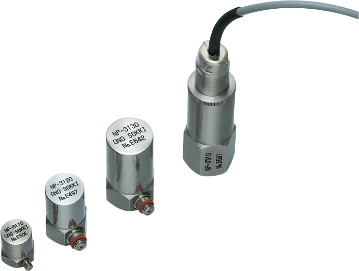
NP-3000 series Accelerometer
The piezoelectric vibration detection method detects vibration caused by the up and down movement of the piston. Due to its high sensitivity and wide frequency range, it is possible to measure rotational speed even with smaller vibrations. It can also be used in diesel engines.
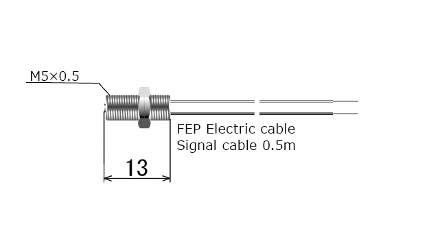
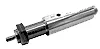
MP-992 Ultra compact Electromagnetic Detector
The rotational speed is detected by electromagnetic induction of leakage magnetic flux from the rotating shaft of a motor or magnet ignition engine. The compact size with a sensor head length of 13 mm allows it to be installed even in narrow spaces. Motor rotation measurement can be performed stably with simple installation.
Enhanced the function to adjust trigger level
This suppresses variations in rotational speed from the start of the engine to high rotational speeds and achieves stable measurements. Also, it is more easy to adjust trigger level. Expands the possibilities for using your existing sensors.
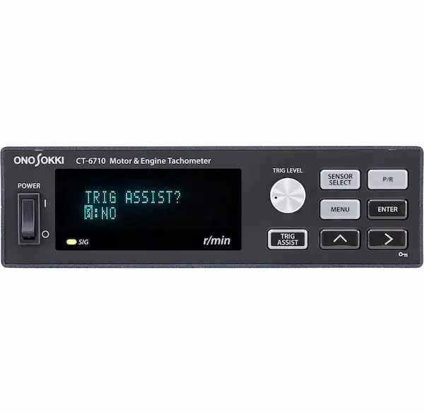
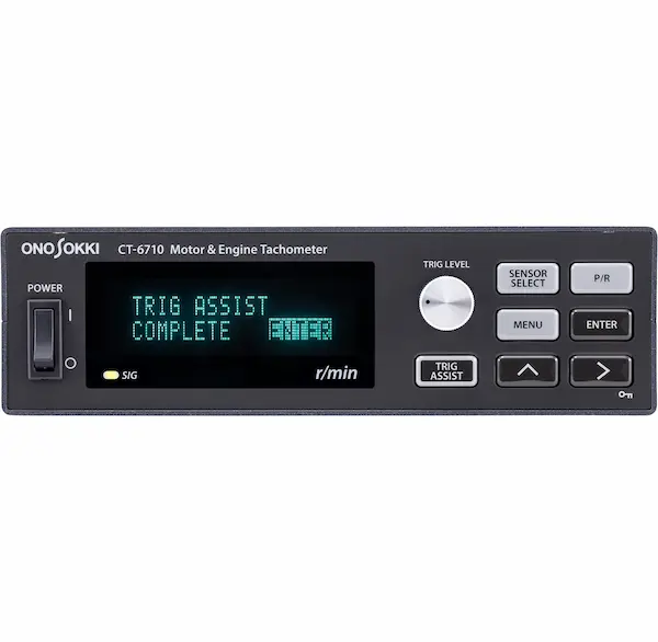
Trigger assist mode
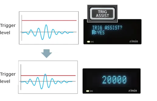
The ignition signal contains noise and induction caused by the ignition of multiple cylinders. By turning on the trigger assist mode, it automatically adjusts to the optimal level to detect only the ignition signal, allowing stable measurement even when the rotation speed is changed.
Trigger level tracking function
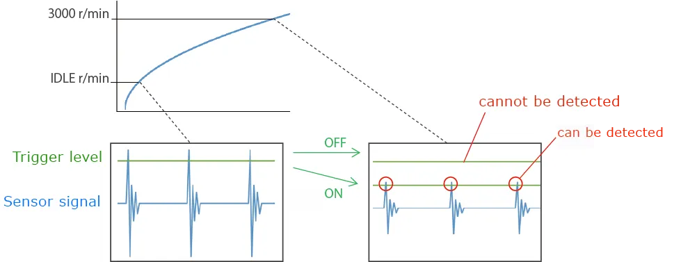
This function reduces the trigger level as the rotation speed increases. Use this when the signal waveform becomes smaller as the rotation speed increases and becomes undetectable. ( for IP series only)
Removing noise signals (Input Division function )
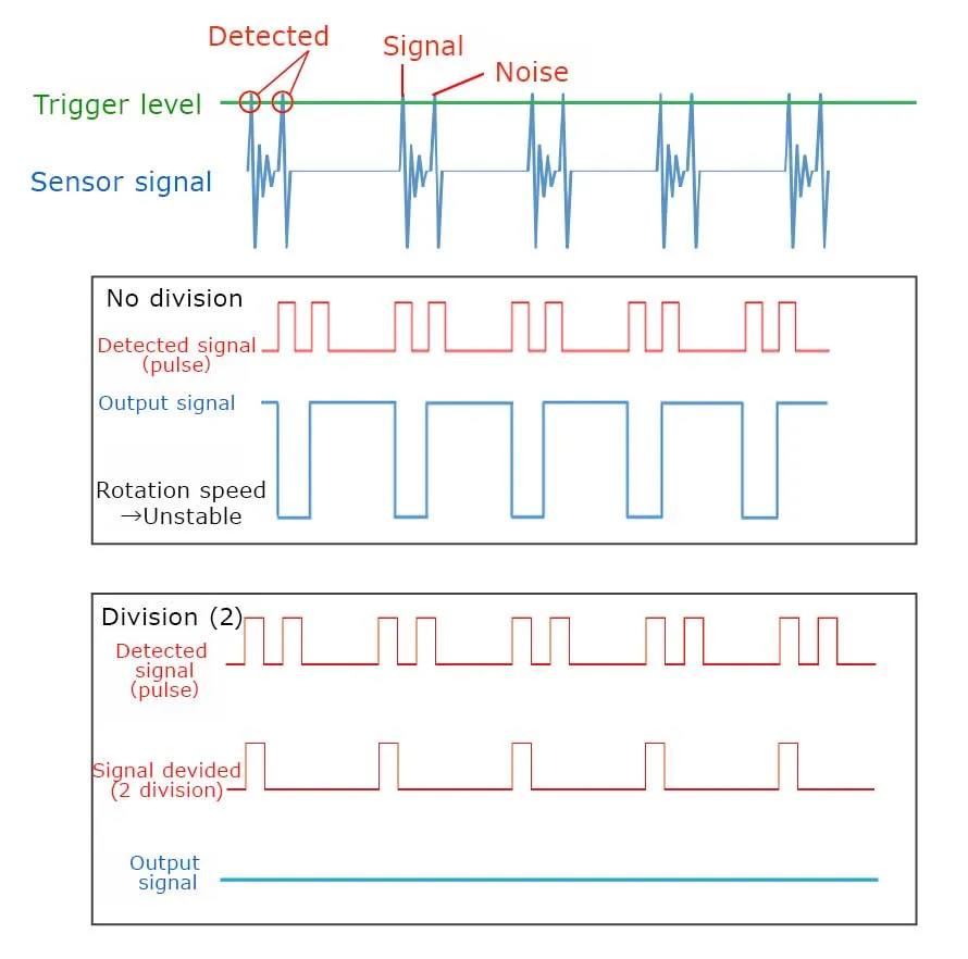
When periodic noise with the same magnitude as the ignition signal is input, it will remain unstable even if the trigger level is adjusted. By using the frequency division function, it is possible to convert to a signal with a constant period and perform stable measurements.
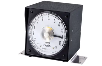
Analog Tachometer CT-0677 (option)
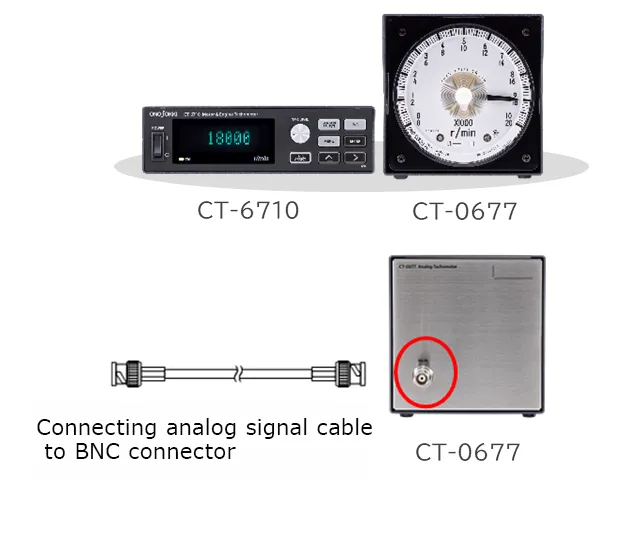
This is a separated meter that is recommended for those who want to see the rotation speed behavior using the meter needle. (Option: CT-0677) There is no need to connect the power to the display, and it can be used easily by simply connecting the analog signal cable (provided as standard accessory).
Various output functions that capture transient phenomena with high-speed response
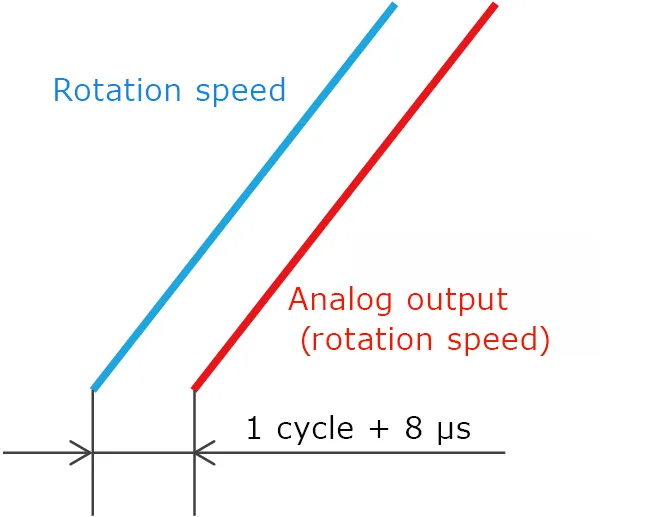
It catches transient phenomena of engine rotation speed with high response. The analog output follows up the behaviors of acceleration/deceleration within 1 cycle + 8 µs of input signal. As for pulse output, waveform-shaped can be output without delay. High speed digital data output by CAN output function (option: CT-0671).
Rotation speed measurement by ECU crank signal
(option: CT-0672)
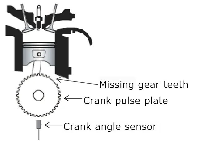
As the crank pulse plate which generates the crank angle signals has additional teeth or missing teeth, the signals are not output equally. Therefore, by learning patterns with irregular intervals, it allows accurate measurements using crank angle signals. (Option: CT-0672)
Light and compact, making it easy to work with
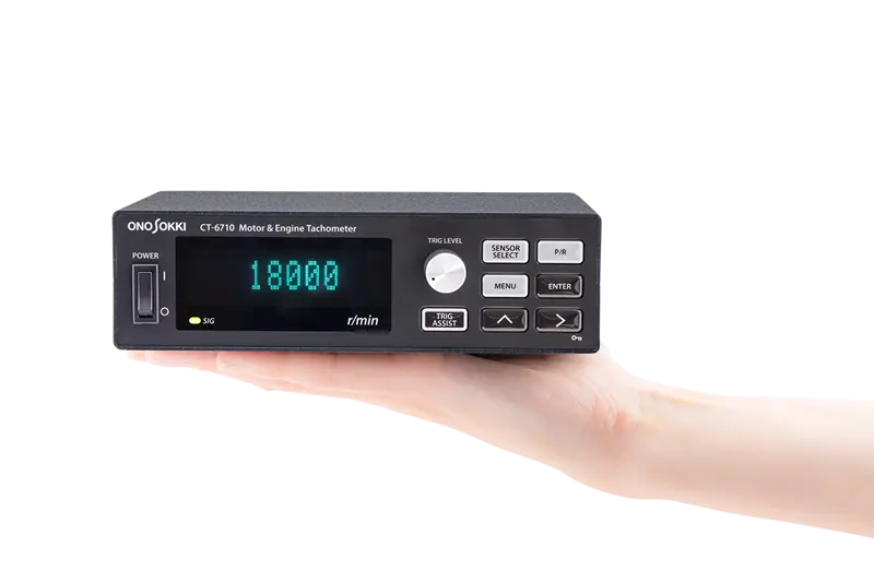
170(W) X 49(H) X 120(D) mm
Pursued compactness and ease of operation so that it can be used not only on an engine bench but also for measurements on an actual vehicle.
Pulse output funcion for tracking analysis
![]()
Tracking analysis can be performed by inputting the DIRECT pulse output of the CT-6710 to our DS series.
Deceleration condition setup function for a sudden engine stop
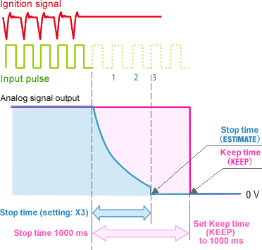
This function sets the stop condition when the detected pulse signals dramatically decrease due to a sudden engine stop, etc. The stop time of estimate calculation (ESTIMATE) function estimate from the last detected signal period, reduces the analog output, and then stops. The keep time (KEEP) sets the analog signal output to 0 V at the specifi ed time.
Comparator function for monitoring engine measurement condition
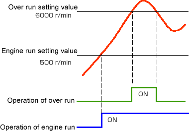
The above is the output operation example of the comparator when the engine run and overrun (VALUE) condition is set. If the engine run is set to 500 r/min, the engine is regarded as started when the engine rotation speed exceeds 500 r/min.
If the overrun is set to 6000 r/min,
the engine is regarded as abnormal when the engine rotation speed exceeds
6000 r/min.
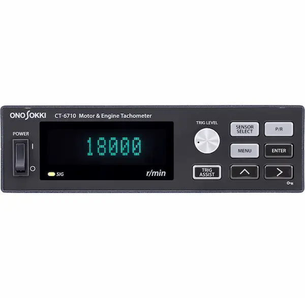
Easy to see, easy to use
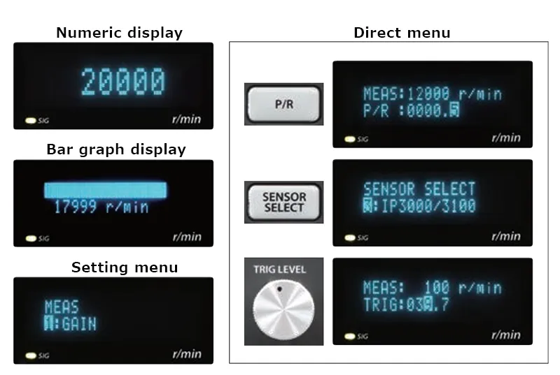
Various functions are easily set by menu format and highly visible display
Frequently-used setting items such as sensor type selection, the number of pulses, and trigger level can be set by direct keys (button and a rotary dial) in a short time.
High speed digital data CAN output function
(option:CT-0671)

| Baud rate (kbps) | 125, 250, 500, 1000 |
|---|---|
| Update frequency (Hz) | OFF, 1, 2, 5, 10, 20, 100, 1000 |
Rotation speed data can be output via CAN interface
Output update frequency is selectable up to 1 kHz. By an instrument with CAN interface such as CAN logger, rotation speed data can be read.
System configurations
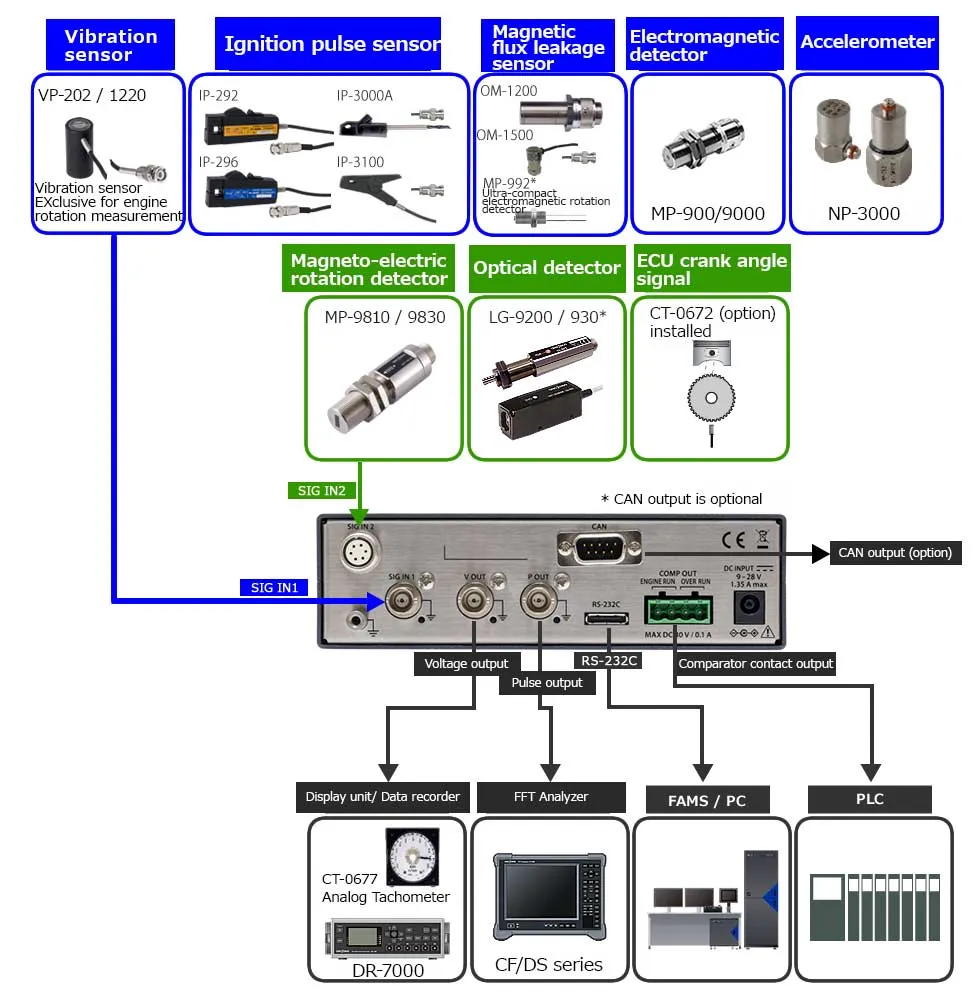
*:The LG-930 cable needs to be processed so that it can be connected.
Contact your nearest Ono Sokki sales office or the distributor where you purchased the equipment.
Specifications
| Input | Applicable sensor/measurement range | IP-292/IP-296/3000A/3100, VP-202/VP-1220, NP-3000 series | 120 to 20,000 r/min |
|---|---|---|---|
| OM-1200/OM-1500, MP-992*1 | 120 to 99,999 r/min | ||
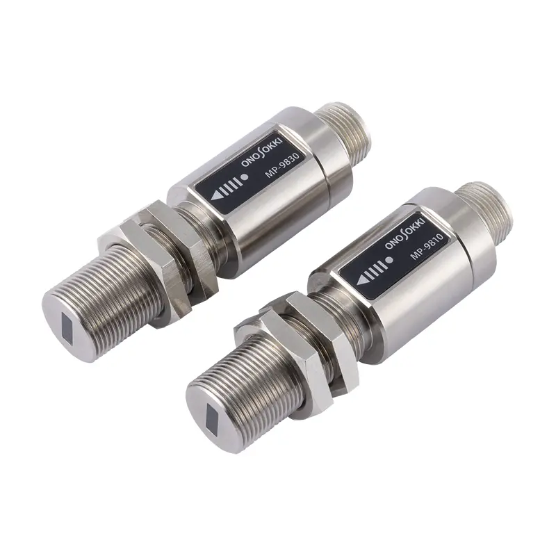
| MP-900/MP-9000 series (Electromagnetic) | 30 to 99,999 r/min | ||
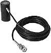
| MP-9810/MP-9830, LG-9200/930*1, EXT(PULSE) | 0 to 99,999 r/min | ||
| ECU crank angle signal (optional) | 120 to 20,000 r/min | ||
| Sensor power supply (R03-PB6M) | 12 V ± 10% (100 mA or lower) | ||
| CCLD power supply (BNC) | 18 V±1 V, 2.4 to 4.5 mA | ||
| Current supplied coaxially to constant current drive sensor using the input connector (BNC) | |||
| Input frequency range | 0.1 Hz to 120 kHz For EXT (Pulse) | ||
| Display | Display method | Vacuum fluorescent display | |
| Display size | 52.5 mm×11.5 mm | ||
| Display Item | Rotation speed (r/min) (average value) | ||
| Displayable range | 0 to 99,999 r/min | ||
| Accuracy | Within ±0.01% FS (±1 count) | ||
| * Factor value: 1.0000E + 0 | |||
| Display status | SIG LED: Light each time when input signal is detected. | ||
| Number of display digits | 5 max. | ||
| Number of digits after the decimal point | Selectable from OFF, one digit after the decimal point | ||
| Analog output | Number of output points | 1 (BNC Connector) | |
| Output item | Rotation speed (r/min) | ||
| Output range | 0 to 10 V | ||
| Range setting | 1 to 99,999 r/min (set in steps of 1 r /min) | ||
| 0.1 to 9,999.9 r/min (when the decimal point is set to be displayed) | |||
| Load resistance | 100 kΩ or higher | ||
| Response | Updates in less than 8 μs after cycle becomes stable. | ||
| accuracy class | 1.5 | ||
| Resolution | 16 bit | ||
| Pulse Output | Number of output points | 1 (BNC Connector) | |
| Output item | DIRECT (Wave-shaped output), 0.5/1/60[P/R] | ||
| Signal level | 0 to 5 V logic signal (Lo: 0.4 V or lower, Hi: 4.5 V or higher) | ||
| Load resistance | 100 kΩ or higher | ||
| Comparator Output | Output item | Engine run, Over run | |
| Output range | 1 to 99,999 r/min | ||
| 0.1 to 9,999.9 r/min (when the decimal point is set to be displayed) | |||
| Contact capacity | 30 VDC/0.1 A | ||
| Connector (Terminal block) | Phoenix Contact MVSTBR2,5/4-ST-5,08 | ||
| RS-232C | Transfer rate | 9600 bps/38400 bps | |
| Connector | ST60-18P(30) (Hirose Electric) | ||
| Dedicated cable | PS-D10758 | ||
| CAN (Optional CT-0671 CAN Output) |
Output item | Rotation speed (r/min) | |
| Baud rate | 125 kbps/250 kbps/500 kbps/1 Mbps | ||
| Frequency of updating output | OFF/1 Hz/2 Hz/5 Hz/10 Hz/20 Hz/100 Hz/1 kHz | ||
| Connector | D-SUB9-pin (male) | ||
| Other Functions | Moving average | 2 to 720 times | |
| Deceleration calculation | Selection of time or cycle | Time: 1 to 1200 ms Cycle: ×1.5 / ×3 / ×5 / ×8 / ×16 |
|
| Pulse division | 1 to 120 | ||
| Trigger assist | Automatic setting of trigger level employed until pulse detection | ||
| Trigger assist | Automatic setting of trigger level employed until pulse detection | ||
| Trigger level follow-up | Varies the trigger level according to the input frequency (dedicated function when IP sensor is selected) | ||
| Resume function | Preserving condition values even while power is off | ||
| Condition memory | Maximum of five types of condition memory can be saved. | ||
| General specifications | Power supply | 9 to 28 VDC, 1.35 A or lower | |
| Outside dimensions/weight | 170 (W) ×49 (H) ×120 (D) mm/Approximately 700 g | ||
| Operating temperature /humidity range | 0 to +50 ℃*2/5 to 80 %RH (no condensation) | ||
| Storage temperature/humidity range | -10 to +60 ℃/5 to 85 %RH (no condensation) | ||
| Conforming Standards | CE Marking | Low Voltage Directive 2014/35/EU: 2014/35/EU Standard EN 61010-1 | |
| EMC Directive: 2014/30/EU Standard EN 61326-1 Class 1 industrial environment | |||
| RoHS Directive: 2011/65/EU Standard EN IEC 63000 | |||
| FCC | 47 CFR 15 Subpart B Class A | ||
| Accessories | Rubber feet x 4, AC adapter (100 to 240V), Instruction manual | ||
*1 MP-992 uses direct FEP wire. We offer custom cable processing. Contact your nearest Ono Sokki sales office or the distributor where you purchased the equipment.
*2 AC adapter operating temperature range: 0 to 40°C
CT-0677 Analog tachometer
| Display unit | 100 mm square wide-angle display | |
|---|---|---|
| Meter scales | 0 to 10,000 r/min 0 to 20,000 r/min (Dual scale) |
|
| Input specifications | 0 to 10 V/0 to FULL (scale) | |
| Input connector | BNC-J | |
| Outside dimensions/weight | 115 (W) ×115 (H) ×150 (D) mm (not including protrusion) /Approximately 1.1 kg | |
| Operating temperature /humidity range | 0 to +50 ℃*/5 to 80 %RH (no condensation) * Assured accuracy range: 5°C to 40°C |
|
| Storage temperature/humidity range | 10 tp +60 ℃/5 to 85 %RH (no condensation) | |
| Conforming Standards | CE Marking | EMC Directive: 2014/30/EU Standard EN 61326-1 Class 1 industrial environment |
| RoHS Directive: 2011/65/EU Standard EN IEC 63000 | ||
| Accessories | Connection cable, Fixing bracket x 1, Fixing bracket screw x 2, Rubber feet x 4, Instruction manual | |
Options
| Model name | Product name |
|---|---|
| CT-0671 | CAN output function |
| CT-0672 | ECU Crank Angle Signal Input Function*3 |
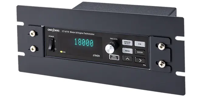
| CT-0673 | Panel Mounting Fixture |
| CT-0674 | Panel Mounting Fixture (CT-6520 replacement)*4 |
| CT-0675 | Protection Plate |
| CT-0676 | Light Shielding Hood |
| CT-0677 | Analog Tachometer |
| LC-0082 | Battery Power Cable |
| LC-0865 | Power cable for Cigarette Lighter Socket Sensor |
*3 This function enables measurement of engine rotation speed by using ECU crank angular signal.
*4 CT-0673 is required when CT-0674 is used.
CT-0673
Panel Mounting Fixture
(not including CT-6710)
CT-0674
Panel Mounting Fixture
for CT-6520 replacement
(not including CT-6710)
CT-0675
Protection Plate
(not including CT-6710)
CT-0676
Light Shielding Hood
(not including CT-6710)
CT-0677
Analog Tachometer
Compatible sensors
For details, click the product name. (Sensors are sold separately.)


Related information
Revised: 2024/06/24