Advanced Handheld Tachometer
FT-7200
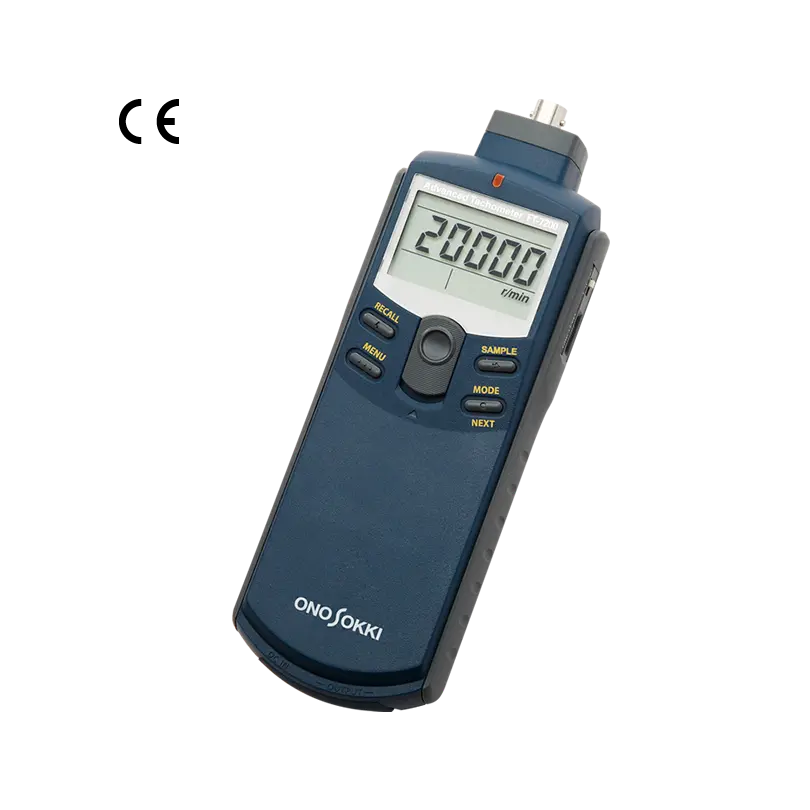
The FT-7200 Advanced Tachometer is an easy-to-use handheld digital tachometer offering high functions and performance. The use of FFT (Fast Fourier Transform) technology enables the FT-7200 to perform frequency analysis of rotation speed by using change of signal in sound, vibration or magnetic flux from rotating machines such as a motor or the like. Selection from 5 kinds of measurement modes allows it to calculate and display rotation speed of any complex waveform signals from a sound level meter or an accelerometer accurately by extracting the exact frequency component.
The FT-7200 enables non-contact measurement of rotation speed by sound or vibration from a measurement object with inaccessible rotating shaft such as a built-in motor in a product, which disabled using conventional tachometers. No need for affixing a reflection mark or modification to a rotating shaft of a measurement object.
Also the use of new algorithm allows calculation and displaying with high follow-up performance, even a sudden change of rotation speed in rising/falling edge of a motor or accelerated/decelerated engine rotation, which has been disabled with conventional models. The FT-7200 is a battery-operated and easy to carry handheld tachometer facilitating on-site measurement.
The FT-7200 can be used with various optional detectors by Ono Sokki; microphone and sound level meter, accelerometer and engine revolution detector, ignition pulse detector and so on. Selectable from wide range of detectors depending on your requirements.
*Please prepare batteries for power supply by yourself.
Features
- Compact and handheld type tachometer with FFT calculation technology
- 5 kinds of algorithms in 2 measurement modes can be selected depending on measurement requirement.
- Provided with the measurement algorithm to follow up a sudden change of rotation speed in rising /falling edge or accelerated/decelerated rotation.
- Enables calculation and display of rotation speed by sound or vibration from a measurement object with inaccessible rotating shaft.
- Non-contact rotation measurement of a thin rotating shaft in a micro motor or fan blades.
- Various detectors are available to cover wide measurement requirements.
- Provided with an analog output and averaging functions.
- Large size LCD with backlight for displaying the measured result.
FT-7200 Demonstration - RPM measurement by using the accelerometer (YouTube)
Measurement mode
5 kinds of algorithms in 2 measurement modes can be selected depending on measurement requirement. C, D and E modes follow up changes in accelerated/decelerated rotation speed. Even when the maximum peak frequency is lost, the peak value is predicted and the rotation speed can be calculated in the C mode. The D mode can follow up changes of the maximum peak and appropriate rotation speed can be selected from up to 8 frequency peaks in the E mode.
| Measurement mode | MODE | Measurement algorithm |
|---|---|---|
| Steady rotation measurement (Constant) (This mode is effective when rotating speed of a measurement object is constant.) |
A | Maximum power spectrum peak detection method |
| B | Peak-interval mode method | |
| Acceleration/deceleration rotation
measurement (Active)
(This mode is
effective when rotating speed of a
measurement object changes.) |
C | Maximum power spectrum peak detection method (Multi-order peak follow-up method) |
| D | Maximum power spectrum peak detection method (Maximum power spectrum peak follow-up method) |
|
| E | Maximum power spectrum peak detection method (Specific power spectrum peak follow-up method) |
The frequency intervals of the order component of the rotation are sought sequentially. The most often appeared frequency interval is judged to be the 1st-order component of the rotation speed. This method is effective to judge the rotation speed and to use when the 1st-order peak is unstable.
The peak frequency of an optional one power spectrum is observed among up to 8 power spectrums for rotation speed measurement.
-- Comparison of the new mode C of the FT-7200 with a previous model --
The mode C of the
FT-7200 enables measurement of rotating object
which cannot be measured before. (Fig.1)
The
performance is improved to follow up a sudden
change of accelerated/decelerated
rotation.(Fig.2)
(Compared analog outputs by oscilloscope)
Rpm measurement of the motor
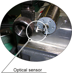
Rpm measurement from vibration
Rpm measurement
from the magnetic flux leakage
Rpm
measurement
from cigarette lighter socket sensor
(*Cigarette Lithter Socket Sensor FT-0801 has been dicontinued.)
Application examples
Using a microphone or an accelerometer to measure rotation speed of an engine
The rotation speed of an engine can be measured from sound or vibration caused by the movement of pistons. This is an effective measurement method when an engine compartment is covered, and engine rotation sensors cannot be attached.
-
Set the number of pulses to match the number of ignition firings per one crankshaft rotation.
Example: In the case of a four-cylinder engine with four-cycle, the number of pulse is set at 2 P/R.
Measuring rotation speed of DC motors built in home appliances
This example shows how to measure rotation speed of DC motors that are built in home appliances. Rotation speed of a motor deeply inside in home appliance, such as an electric toothbrush, can be obtained by magnetic flux leaking from the motor.
-
The rotation speed can be measured simply by inputting the number of poles in a DC motor rotor.
Using an engine rotation sensor to measure rotation speed of an engine
The rotation speed of an engine can be measured by clamping a sensor to the primary side of low-voltage or secondary side of high-voltage conductor. Measurement can be performed simply by inputting the number of ignitions per rotation.
-
Set the number of pulses to match the number of ignition firings per one rotation.
Example: In the case of a 4-cycle engine
If you will be performing measurement on the primary conductor, set the number of pulses to half the number of cylinders. If you will be performing measurement on the secondary conductor, make the setting 0.5 P/R so that there is one pulse for every two rotations.
Using an accelerometer to measure rotation speed of a small fan
This example shows how to measure rotation speed of rotating objects such as a small fan. The vibration from a rotating object depends on rotation movement of an object. The rotation speed of an object can be obtained by measuring the vibration frequency.
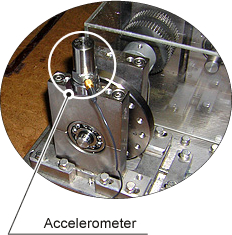
Using an accelerometer to measure rotation speed of a compressor
This example shows how to measure rotation speed of compressors used in air conditioners or similar equipments. The FT-7200 can measure rotation speed of a compressor with inaccessible rotating shaft in combination with an accelerometer.
Using a microphone to measure rotation speed of an engine from the muffler noise
This example shows how to measure rotation speed of an engine from an vehicle's muffler noise. Since pulsation component of engine rotation is included in muffler noise, the engine's rotation speed can be obtained by this pulsation frequency component.
-
Set the number of pulses to match the number of ignition firings per one crankshaft rotation. Please note, however, that depending on muffler performance, there may be cases when measurement cannot be performed.
Using a Cigarette Lighter Socket Sensor FT-0801* to measure rotation speed of an engine
(*Cigarette Lithter Socket Sensor FT-0801 has been dicontinued.)
In this example, the FT-7200 measures rotation speed of an engine by using ignition noise from power outlet in vehicle, which is detected by the FT-0801. It can be used for voltage at 12VDC and 24VDC.
Overview Specifications
| Measurement Section | |||||||||||||||||||
|---|---|---|---|---|---|---|---|---|---|---|---|---|---|---|---|---|---|---|---|
| Measurement object | DC motor, compressor, engine or other general rotating objects | ||||||||||||||||||
| Calculation method | FFT calculation method | ||||||||||||||||||
| Measurement time | 250 ms or less | ||||||||||||||||||
| Input frequency range |
(at 1 P/R ) |
||||||||||||||||||
| Measurement unit | r/min (rotation speed) | ||||||||||||||||||
| Measurement accuracy | ±2 x rotation speed resolution (r/min), ±1 count * The rotation speed accuracy depends on the frequency range. |
||||||||||||||||||
| Minimum rotation speed resolution | Frequency range (Hz) ÷ 6400 x 60 ÷ the number of pulses set (P/R) * The resolution becomes coarse when the
rotation speed is accelerating or decelerating. |
||||||||||||||||||
| Filter function | Limited to the frequency range that you want to measure (rotation speed range) from the overall range of the selected frequency range | ||||||||||||||||||
| Averaging function | Moving average No. of averages: OFF, 2, 4, 8, 16 |
||||||||||||||||||
| Sensor amplifier sensitivity adjustment dial | The sensor amplifier sensitivity can be adjusted by using the rotary dial located on the right side of the main unit. | ||||||||||||||||||
| Detection section | |||||||||||||||||||
| Applicable detector |
* Please note, however, that detection may not be performed correctly depending on the engine or measurement object. |
||||||||||||||||||
| Voltage level |
5 V :Max ± 5 V 0.5 V :Max ± 0.5 V 0.05 V:Max ± 0.05 V |
||||||||||||||||||
| Input coupling | AC coupling | ||||||||||||||||||
| Power supply for NP sensor | Constant Current Power Supply (2.4 ±0.5 mA) | ||||||||||||||||||
| Display section | |||||||||||||||||||
| The number of display digits | 5 digits | ||||||||||||||||||
| Character height | 10.2 mm | ||||||||||||||||||
| Display | 7-segment LCD with backlight | ||||||||||||||||||
| Display update time | 0.5 ± 0.2 seconds | ||||||||||||||||||
| Display resolution | 1 r/min | ||||||||||||||||||
| Measurement mode section | |||||||||||||||||||
| CNS(Constant) |
|
||||||||||||||||||
| ACT(Active) |
|
||||||||||||||||||
| Analog output section | |||||||||||||||||||
| 【REVO】Analog output |
|
||||||||||||||||||
| 【SIG】Analog output for monitor |
|
||||||||||||||||||
| Pulse output section | |||||||||||||||||||
| Output signal | Frequency pulse of power spectrum extracted with FFT processing | ||||||||||||||||||
| Output voltage | Lo: 0.5 V or less, Hi: 4.5 V or more(with no-load) | ||||||||||||||||||
| Output update time | Steady rotation measurement mode(Constant):500 ms or
less Rotation acceleration/deceleration measurement mode (Active):250 ms or less |
||||||||||||||||||
| Load resistance | 100 kΩ or more | ||||||||||||||||||
| Output connector | Ultra-mini jack (Φ2.5, same which is also used as REVO output.) | ||||||||||||||||||
| General specifications | |||||||||||||||||||
| Power source | Type AAA battery cell x 4 pcs*. or PB-7090 exclusive AC adapter (option) | ||||||||||||||||||
| Continuous operating time | Approx. 6 hours (when the backlight
is off.) *1: When an NP series accelerometer is used, current consumption increases because of the constant current power supply used to drive the NP series accelerometer. Use of the exclusive adapter is therefore recommended. |
||||||||||||||||||
| Battery LOW display | The "LOW" mark flashes when the voltage has dropped to approx. 4.2 V. | ||||||||||||||||||
| Operating temperature range | 0 to +40 °C | ||||||||||||||||||
| Storage temperature range | -10 +50 °C | ||||||||||||||||||
| Operating humidity range | +35 to +85 %RH (with no condensation) | ||||||||||||||||||
| Storage humidity range | +35 to +85 %RH (with no condensation) | ||||||||||||||||||
| Outer dimensions | 189.5(L)× 66(W)× 47.5(D)mm (main unit only) | ||||||||||||||||||
| Weight | Approx 230 g (main unit only; not including batteries) | ||||||||||||||||||
| Conforming standard(CE marking) | |||||||||||||||||||
| Low Voltage Directive | 2014/35/EU, EN61010-1 | ||||||||||||||||||
| EMC Directive | 2014/30/EU, EN61326-1 | ||||||||||||||||||
| RoHS Directive | 2011/65/EU, EN IEC 63000 | ||||||||||||||||||
| Accessories | Carrying case, Instruction manuals (3 kinds) | ||||||||||||||||||
*Please prepare batteries by yourself.
Options
| Ignition pulse detector (Primary side) IP-292
|
Ignition pulse detector (Secondary side) IP-296 |
Ignition pulse detector IP-3000A
|
Ignition pulse detector IP-3100
|
| Motor/gasoline
engine RPM detector OM-1500/1200 |
DC motor rotation detector FT-0501 |
Piezoelectric-type accelerometers NP-2000/NP-3000 Series
* Charge amplifier is required |
Microphone + preamplifier MI Series
|
| Engine rotation detector VP-202 |
Engine revolution detector
(High-sensitive type) VP-1220 |
Cigarette lighter socket sensor FT-0801 (Discontinued)
Input voltage:12 or 24 V |
|
| Magnetic stand/stand jig HT-0522/HT-0521B
|
Tripod (Airy L100 made by SLIK Corporation) |
AC adapter PB-7090
|
Analogue output signal cable
(2 m) AX-501
|
Related information
Revised:2025/04/10