Advanced Tachometer FT-2500
Easy measurement of rotation speed from sound and vibration
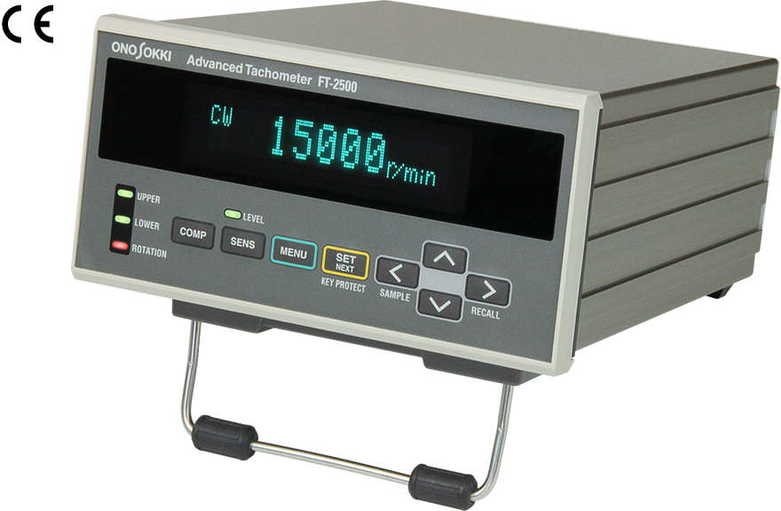
FT-2500 advanced tachometer measures the rotational speed by using the signal of change in sound, vibration or magnetic flux from rotating machines such as motor or the like.
The use of FFT technology enables the FT-2500 to calculate and display the rotational speed of any complex waveform signals from microphone, sound level meter or vibration sensor by extracting the frequency component which is equivalent to the rotational speed.
The FT-2500 has several advantages over conventional tachometers. Even though the rotating shaft is not accessible, it allows easy evaluation of the rotation object such as motor which has already been built in product. There is no need to affix reflective mark to the measurement object or special machining to the rotating shaft. A newly developed algorithm is incorporated in the FT-2500 so that not only the steady rotation of motor or engine but also the status of the accelerated/decelerated rotation can be measured with high response.
Video | Measurement Example: Compressor
Features
Measurement mode
The measurement algorithm can be selected from the following five modes depending on the rotational condition. The C, D, and E modes follow acceleration and deceleration by processing internal processing at high speed. In the C mode, it predicts the peak value which it should be and calculates the rotational speed even if the maximum peak has been missed. In the E-mode of rotational speed candidate selection, the optimum rotational speed can be selected from maximum of 8 frequency peaks.
| Measurement Mode | MODE | Measurement algorithm |
|---|---|---|
| Steady rotation Measurement Mode
(This mode is effective when the rotational speed of the measurement object is constant.) |
A | Maximum power spectrum peak detection method |
| B | Peak-interval mode method | |
| Rotation Acceleration/Deceleration Measurement Mode (ACT)
(This mode is effective when the rotational speed of the measurement object changes.) |
C | Maximum power spectrum peak detection method (Peak prediction) |
| D | Maximum power spectrum peak detection method | |
| E | Maximum power spectrum peak detection method Rotational speed candidate selection function |
Maximum power spectrum peak detection method
This mode is calculated by the frequency of the power spectrum's maximum peak. Measurement is usually performed in this mode.
Peak-interval mode method
In order to fix the rotational speed, the frequency intervals of each order component are sequentially obtained and the most often appeared frequency interval is judged as the 1st order component of the rotational speed. It is effective method when the 1st order peak is unstable.
Rotational speed candidate selection function
Measure by focusing on any one of the frequency peaks of up to 8 power spectra.
Application examples
Rotational speed measurement of a DC motor with the micro rotating shaft
The rotational speed of a DC motor can be measured without attaching the reflective mark on the surface of the shaft. This example allows the rotational speed measurement of the fan, which shaft is too thin that reflective mark can not be attached or optical light can not be reflected straight when optical sensor is used.
Determining of rotating direction and rotational speed measurement of a general DC motor
It is an example to determine the rotating direction and measure the rotational speed of a DC motor by using the FT-0501 DC Motor Rotation Detector. The FT-0501 detects the magnetic flux leakage of a DC motor and extracts a frequency signal in proportion to the rotational speed.
Since the FT-0501 has two internal coils, a phase shift occurs between the two detected signals. The rotating direction is then determined by the relationship of these two phases. This function is very convenient for quality control of small DC motors, whose rotating directions may be difficult to be determined visually. Of course, it can measure the rotational speed.
Rotational speed measurement of a compressor using an accelerometer
With a combination of the FT-2500 and suitable accelerometer, the rotational speed of a compressor in the refrigerator, vending machine, air conditioner etc, which shaft is not directly accessible, can be measured easily. Put an accelerometer (NP-3000 series) on an optional magnet base (NP-0100 or NP-0101) and check the signal at various locations. And then place it at an optimum position on the compressor.
Rotational speed measurement of a DC motor in a fuel pump using a current probe sensor
Many DC motors are mounted in automobile electrical equipment.
The consumption current of the DC motor pulses in proportion to the number of poles in the motor.
The rotational speed of the DC motor can be accurately measured by inputting the current signal
which is detected by the current probe sensor to the FT-2500.
This example is ideal for measuring the rotational speed of a stand-alone DC motor or
products (parts) that incorporate motors whose lead wires are accessible, such as those
found in automobile electrical equipment.
Rotational speed measurement of a pump using sound pressure
A pump’s rotational speed is easily measured by monitoring exhaust sound. The rotating shaft in a pump is generally not exposed externally, making it difficult to perform measurement of the rotational speed by the ordinary and conventional pulse detection method. In this example, the sound pressure of the exhaust sound is detected for the rotational speed measurement with a microphone.
Rotational speed measurement of a DC motor which is built in a home appliance
A popular electric toothbrush is operated by converting the rotation of the DC motor into the vibration. The FT-2500 with FT-0501 detector can measure the rotational speed by detecting the magnetic flux leaking from the DC motor which is built in such product.
Rotational speed measurement of an engine using a microphone or an accelerometer
The FT-2500 can measure the rotational speed of an engine by the sound and vibration related to the movement of the pistons. It is effective when the rotational sensor cannot be attached because the engine compartment is covered.
Rotational speed measurement of an engine using an engine rotational sensor
The rotational speed of an engine can be measured by clamping a sensor to the primary low-voltage or secondary high-voltage conductor. Measurement can be performed simply by inputting the number of ignitions per rotation.
Rotational speed measurement of a small fan using an accelerometer
It measures the rotation speed of a rotating body such as a small fan. The vibration of the rotating object depends on the rotational motion. By measuring the frequency of vibration, the rotational speed of the rotating object can be obtained.
Rotational speed measurement of an engine from muffler’s sound collected by a microphone
This example shows how to measure the rotational speed of an engine from muffler’s sound. Since the pulsation component of the engine rotation is included in the muffler’s sound, the engine's rotational speed can be obtained by the frequency component of this pulsation
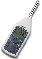
Rotational speed measurement of a vacuum cleaner using a sound level meter
>Even if a motor is not visible like a vacuum cleaner, it measures the rotational speed of a motor from the operating noise.
Rotational speed measurement of a dryer and an electric drilling machine using an accelerometer
By the rotational vibration, the FT-2500 can measure the rotational speed of a motor which is built into the dryer, electric drilling machine or the similar equipment even though the motor is not accessible.
Rotational speed measurement of an engine using a cigarette lighter socket sensor
Connect the sensor to a power outlet in a car or construction machine. With the FT-2500,
you can determine rotational speed of the engine by measuring the ignition noise from the power outlet.
Can be used with both 12 and 24 VDC batteries.
(*Cigarette Lithter Socket Sensor FT-0801 has been dicontinued.)
Simultaneous measurement of rotating speed and direction of a fuel pump
This example shows how to make rotating speed measurement and rotation direction determination of a finished fuel pump simultaneously, which is widely used such as in a vehicle. Since the rotating shaft is not come out, it is difficult to make direct measurement by attaching a sensor to the rotating shaft. The rotating speed and direction of the motor built in a fuel pump can be measured by the FT-2500 advanced tachometer with the FT-0501 magnetic flux leakage sensor. The FT-0501 attached to the fuel pump detects the magnetic flux leakage, and the FT-2500 performs frequency calculation of the magnetic flux changing periodically.
Outline Specification
| Input section | |
|---|---|
| Applicable sensor | FT-0501/FT-0801*, IP-292/IP-296, IP-3000A/IP-3100, VP-202/VP-1220, OM-1500/OM-1200 Constant Current Line Drive sensors, microphones, accelerometers and so on. |
| Measurement section | |
| Measurement mode | 1.Steady rotation measurement
mode ・Frequency range: 500 Hz, 2 kHz, 10 kHz ・Resolution =Frequency range ÷ 12800 × 60 ÷set pulse count 2.Rotation acceleration/deceleration measurement
mode |
| Rotating direction acknowledgment | Available when FT-0501 is in use. |
| Measurement accuracy | ±2 x rotating speed resolution ±1 count |
| Averaging processing | Moving average processing, allowable count: OFF, 2, 4, 8, 16 |
| Filter function | Can be set voluntary (Specifying each one of upper and lower rotating speeds.) |
| Display section | |
| Display update time | 0.5 ±0.2 second |
| Measurement display range | 0 to 999,999 r/min(0 to 10,000 Hz) |
| Output section | |
| Analog output voltage range | 0 to 10 V/0 to F.S. Rotational speed can be specified voluntary at 10 V output. |
| Analog output update time | Steady rotation measurement
mode: 500 ms or less Rotation acceleration/deceleration mode: 250 ms or less |
| Sensor signal output for monitoring | Sensor signal output for
monitoring (The output can be selectable from analog or monitor output.) |
| Comparator output | Upper/lower-limit
determination, rotating direction acknowledgment, OK
determination Output method: semiconductor relay (3 circuits are built-in.) |
| Pulse output | Output the frequency
equivalent to the displayed rotational speed x set P/R (Hi: 4.5 V or more, Lo: 1 V or more) |
| External interface | RS-232C, External command input connector |
| Memory section | |
| Condition memory | Saving 3 kinds of setting conditions. |
| Conforming standard(CE marking) | |
| Low Voltage Directive | 2014/35/EU, EN61010-1 |
| EMC Directive | 2014/30/EU, EN61326-1 |
| RoHS Directive | 2011/65/EU, EN IEC 63000 |
| General specifications | |
| Power requirement | 100 to 240 VAC(50/60 Hz) |
| Power consumption | 32 A or less |
| Operating temperature range | 0 to +40 °C |
| Storage temperature range | -10 to +55 °C |
| Outer dimensions | 144(W) × 72(H) × 180(D) mm |
| Weight | Approx. 2 kg or less |
| Accessories | Panel mounting fixture, stand foot, rubber foot, connector (D-SUB <15-pin, plug>), Power cable (3P-3P, 1.9-m) .......... (1 pc. for each) |
| Option | AX-5022B RS-232C cable
FT-0100 Analog output cable(1.5m R03PB3M-BNC245) FT-0110 Pulse output cable(1.5m D-SUB15PIN-BNC245) FT-0251 Ethernet communication function : Discontinued (RS-232C function cannot be used when Ethernet option is equipped.) |
Caution!
The FT-2500 uses non-volatile memory to
store parameters. A non-volatile memory
has a limitation of rewritable
frequency. Under general using
condition, the number of rewriting will
not exceed 1 million times which is the
maximum rewritable times of the
non-volatile memory used in this model.
However, it shall not be applied with
the case which you often send a
numerical value setting commands via
RS232C. If [MEMORY Error!] appears, it
is the sign that the memory has a
trouble and needs memory replacement
(fare-paying). Please contact your
nearest distributor or send us an e-mail
(overseas@onosokki.co.jp).
* FT-0801 is discontinued
Applicable sensors (option)
| Ignition pulse detector (Primary side) IP-292
|
Ignition pulse detector (Secondary side) IP-296
|
Ignition pulse detector IP-3000A
|
Ignition pulse detector IP-3100
|
| Motor/gasoline engine RPM detector OM-1500/1200 |
DC motor rotation detector FT-0501
|
Piezoelectric-type accelerometers *1 NP-2000/NP-3000 Series
|
Microphone+preamplifier MI Series
|
| Engine rotation detector VP-202/ VP-1220 |
Sound level meter |
Cigarette lighter socket sensor FT-0801 Discontinued
|
*1 Charge amplifier is required additionally when NP-2000 series accelerometer is used.
Related information
Last update : 2025/04/10