Laser Doppler Vibrometer LV-1800
Laser Doppler vibrometer with No load and Non-contact
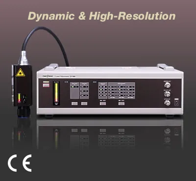
The LV-1800 non-contact type Laser Doppler Vibrometer uses newly designed interference optical system
and has achieved improvement of detection sensitivity by 20 dB compared to the conventional models.
The built-in positioning camera makes it easy to check the target by laser beam irradiation.
The LV-1800 can perform amplitude velocity measurements in a wide range of fields that are difficult with a contact type vibration sensor; small actuator using piezoelectric element, cell phones and digital camera with MEMS (Micro Electro Mechanical Systems), inverter an other devices in an EV/HEV. By using the LV-1800 with FFT Analyzer, it is possible to visualize not just vibration but the state of the vibration.
Features
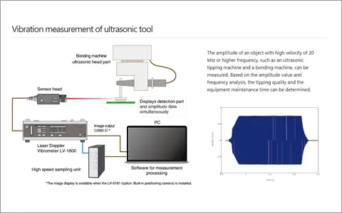
Example of usage
Ultrasonic applied devices
Ultrasonic welding machine, wire bonding machine, ultrasonic cutter,
ultrasonic homogenizer, ultrasonic soldering iron
Ultrasonic microscope, ultrasonic atomizer
Fishfinder, frequency/amplitude measurement of sonar device
Nanoimprinting device, piezoelectric vibrating gyroscopes
Ultrasonic motor, ultrasonic cleaning machine, ultrasonic scalpel
Behavior detection of living body (insect etc.)
IT / mediums
Transmission characteristic of optical pickup (CD· DVD· BD etc.)
Vibration measurement of disc surface
Behavior of ink-jet element
Slider & VCM of HDD,HDD, vibration analysis of flying head and other component
Vibrating thin film in cell phone's microphone, receiver or speaker
Vibrating motor
Ultrasonic motor for AF (autofocus) function in camera
Automobiles(including EV / HEV)
Inverter motor, inverter and its component device, smoothing condenser etc
Rotation tracking analysis of engine, transmission
Shock sensor (MEMS)
Internal vibration of light valve
Differential displacement measurement of brake caliper, fuel injector
Vibration of warning sound alarm
Plant
Valve movement
Long distance vibration of pipework, blower, motor etc
Laser ultrasonics
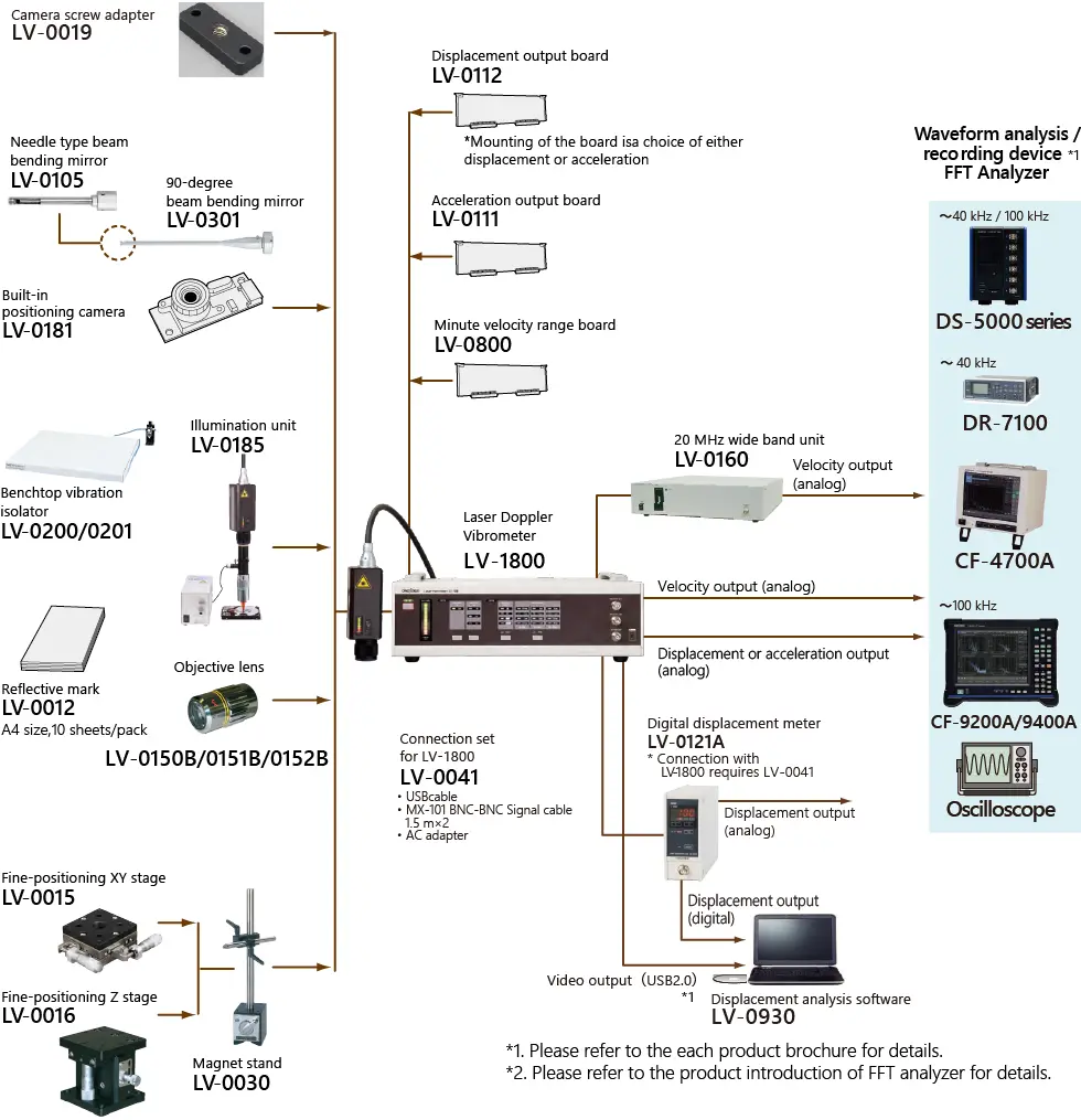
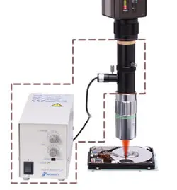
System Configuration
Specifications
Laser Doppler Vibrometer Measurement Range
Detection unit
| Detection demodulation system | Velocity demodulation using optical heterodyne detection | ||
|---|---|---|---|
| Laser beam | Light source | He-Ne laser (=approx.633 nm) | |
| Reflected light output | Within 1 mW | ||
| Laser safety standard | Conforming to Laser Class 2 * Please refer to <conforming standard> for more details. |
||
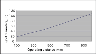
| Minimum laser spot diameter | Approx. 20 μm or less (φ=1/e2 when the focusing position is 100 mm.) | ||
| Approx. 3 μm or less (When the LV-0151B is mounted.) WD=approx. 38.8 mm | |||
| Standard lens | Variable-focus lens | 100 mm to 10 m (∞) | |
| Distance scale | 100 mm to 10 m (∞) *With the coherence length mark | ||
| Size of attachment | M22 x 0.5 Depth 5.5 mm | ||
| Built-in
positioning camera LV-0181 (option) |
Installing method | Built-in the sensor (Can be installed after delivery. Please contact your nearest distributor for more details.) | |
| Interface | USB 2.0 *output from the conversion section USB mini-B connector |
||
| Imaging element | CMOS color 1/4-inch | ||
| Number of pixels | More than 300,000 pixels | ||
| Image size | VGA (640 x 480) | ||
| Frame rate | 30 frames/second | ||
| Minimum imaging range | 10 x 7.5 mm (TYP) WD=100 mm (at minimal length) | ||
| 2.1 x 1.6 mm (TYP) When the LV-0151B objective lens is mounted. | |||
| Imaging position | An erect image when you see the indicator panel of the sensor head (rotatable). | ||
| Exposure | Automatic | ||
| White balance | Automatic | ||
| Gain | Automatic | ||
| Operating environment | Windows® 10/11 Display True Color 24 bit or more | ||
| Camera focus | Adjusted by the objective lens, confocal with the laser spot | ||
| Sensor suspending | Screw for sensor suspension | Backside x1 | M8 depth 8mm *LV-0030 large size magnetic stand can be used. |
| Side x1 | |||
| Side x 2 | M4 depth 5 mm | ||
| Tripod setup | Use the LV-0019 camera screw adapter (option) | ||
| Demodulation sensitivity monitor | Signal level indicator | 10-segment
LED array display * Works with the signal level indicator display on the conversion unit. |
|
| ERROR indicator | LED display (red) | ||
| Signal cable | Cable length | 3 m | The cable is wound up on the cable clamp (rear panel of the conversion unit). |
| Diameter | φ=10.5 mm | ||
| Coating | Oil-resistant coating | ||
| Minimum bend radius | R=40 mm or more | ||
| Outer dimensions of the detection unit | W | 53 mm | Not including the protruded section |
| H | 52.5 mm | ||
| D | 152.5 mm | ||
| Weight of the detection unit | Approx. 750 g (When the LV-0181 is installed. Not including the cable.) |
||
Conversion unit
| Detection velocity | Frequency range | 0.3 Hz to 3 MHz (fc=-3dB) *common to each
velocity range 0.001 m/s/V (option): 0.3 to 200 kHz (fc=-3dB) |
|
|---|---|---|---|
| Maximum detection velocity | 10 m/s o-p (20 m/s p-p) | ||
| Minimum velocity resolution | 0.3 μm/s or less (when at 0.01 (m/s) /v) 0.05 μm/s or less 8when the LV-0800 is installed.) | ||
| Output | ±10 V (20 V p-p) *Input impedance: 100 kΩ or more | ||
| Polarity of output voltage | + voltage when moving closer to the sensor side | ||
| DC offset | 20 mV or less | ||
| Output impedance | 50 Ω | ||
| Minimum input impedance | 100 Ω | ||
| Connector type | BNC (C02) | ||
| Velocity range | 1.0 (m/s)/V | 10 m/s 0-p(20 m/sp-p) | |
| 0.1 (m/s)/V | 1 m/s 0-p(2 m/sp-p) | ||
| 0.01 (m/s)/V | 0.1 m/s 0-p(0.2 m/sp-p) | ||
| 0.001 (m/s)/V (option) | 0.01 m/s 0-p(0.02 m/sp-p) | ||
| Over indicator | Red LED lights up when the detected velocity exceeds + 5% of upper limit. (5 % Over) | ||
| Demodulation sensitivity monitor | Signal level indicator | 20-segment LED
array display * Works with the signal level indicator display on the detection unit. |
|
| MONITOR output | 0 to 10 V | ||
| Output impedance | 50 Ω | ||
| Minimum input impedance | 100 kΩ or more | ||
| Connector type | BNC (C02) | ||
| ERROR indicator | Light up of red LED | ||
| High-pass filter (HPF) | 100 Hz | fc=-3dB | |
| OFF (0.3 Hz) | |||
| Low-pass filter (LPF) | 50 kHz | fc=-3dB
*Not selectable when 0.001 (m/s)/V range is selected. |
|
| 100 kHz | |||
| 1 MHz* | |||
| OFF (3 MHz) | |||
| Image output for positioning (option) | Image output | Digital | |
| Standard | USB2.0 | ||
| Display | Light up of white LED *When the LV-0180 is installed. | ||
| Connector type | USB mini-B type | ||
| Control of laser radiation | ON/OFF by the panel switch on front side | Function of power-on laser irradiation can be specified at time of order. | |
| Laser beam irradiation indicator | *Green LED light up when laser beam is radiated. | ||
| Mechanical shutter | Contact input | The laser beam radiation is stopped at contact open. | |
| Connector type | Receptacle:RM12BRB-2S | ||
| Plug:RM12BPW-2PH | |||
| Storage device | Storage of detection unit | Stored in the conversion unit | |
| Storage of cable | Wound up on the cable clamp (rear panel of the conversion unit). | ||
| Outer dimensions | W | 410 mm | Not including protruded section |
| H | 120 mm | ||
| D | 324 mm | ||
| Weight | Approx. 8.1 kg (including sensor and cable) | ||
| Operating temperature range | 0 to 40°C | ||
| Operating humidity range | 30 to 80 %RH with no condensation | ||
| Storage temperature range | -10 to +50°C | ||
| Input voltage | AC100 to 240 V | ||
| 50/60 Hz | |||
| Power consumption | 60 VA | ||
| Cooling method | Natural air cooling (no-vibration cooling) | ||
Conforming standard
| Laser safty | IEC 60825-1:2007:2014 | |
|---|---|---|
| EN 60825-1:2007:2014/A11:2021 | ||
| FDA (CDRH) 21CFR 1040.10 and 1040.11 except for conformance with IEC 60825-1 Ed.3., as described in Laser Notice No. 56 | ||
| CE marking | Low voltage Directive: 2014/35/EU EN 61010-1, EN 60825-1 | |
| EMC Directive: 2014/30/EU EN 61326-1 | ||
| RoHS Directive: 2011/65/EU EN IEC 63000 | ||
Relation between vibrating direction and voltage output
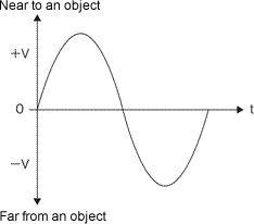
LPF : 100 kHz ON
At maximum demodulation using a corner cube.
Power spectrum observation by FFT Analyzer
1 kHz range 1 kHz, 2048 lines, averaging of 256 times
* Please refer to the above graph for the each filter characteristics.
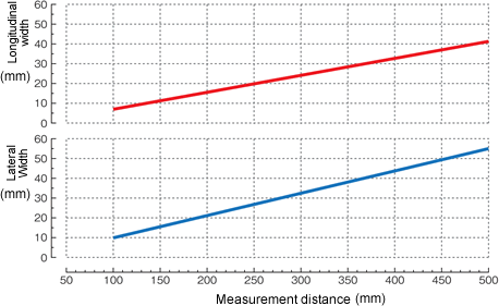
Imaging range taken by the LV-0181 (Built-in positioning camera)
Relation between operating distance and spot diameter
Options
LV-0181 Built-in positioning camera
The LV-0181 is a high sensitivity digital camera to position thesensor head while checking the image of an object. (A camera module is built in the sensor head). The coaxial and confocal camera, in which the focal point of the laser beams and the focus of images are common, displays the images of detected parts on Windows® based PC through USB 2.0 output. The LV-0181 makes it possible to check small measuring objects and also irradiate laser beams speedily. By combining the LV-0151B (objective lens) and the LV-0185 (illumination unit), amplitude of micro objects such as MEMS can be measured.

| Connector type | :USB2.0 (main unit side: mini-B) |
| Imaging element | :CMOS color sensor 1/4 inch |
| Number of pixels | :300,000 pixels or more |
| Image size | :VGA(640×480) |
| Frame rage | :30 frame/second |
| Range of shooting | :10 mm×7.5 mm to (measurement distance 100 mmto) |
| Function | : exposure/gain/white balance(automatic) |
LV-0800 Minute velocity range board
The LV-0800 is a minute velocity range board to be installed to the LV-1800. It enables measurements of those which are hard to be detected in standard measurement ranges such as amplitudes of ceramic capacitors, propagation of ultrasonic waves. By adding the LV-0800, it covers the detection of 0.05 μm/s to 10 m/s velocity amplitudes with 4 ranges.
| Velocity range | :0.001 (m/s)/V (0.01 m/s0-p(MAX)) |
| Velocity resolution | :0.05 µm/s *At maximum modulation |
| Frequency range | :0.3 to 200 kHz (fc = -3 dB) |
LV-0112 Displacement output board/LV-0111 Acceleration output board
When the LV-0112/0111 is built in the LV-1800, it converts the detected velocity (m/s) into displacement (m) or acceleration (m/s2). Signal is output from an optional connector, and the velocity signal and the displacement/acceleration signal can be obtained simultaneously. Either one of the LV-0112 or the LV-0111 can be installed in the LV-1800.
Common specification
| Signal source | :Internally receives the velocity signal from the LV-1800 |
| Output voltage | :±10 V (MAX) |
| DC offset | :20 mV or less |
| Maximum amplitude | :Ten times of an each setup range (0-p) |
| Amplitude conversion error | :±5% or less |
| Amplitude output polarity | :+ Voltage when moving closer to a sensor side. |
Specification of the LV-0112
| Setup range of the LV-1800 |
Frequency range / Displacement range | ||
|---|---|---|---|
| 1 Hz to 20 kHz | 10 Hz to 50 kHz | 1 kHz to 200 kHz | |
| 1.0(m/s)/V | 100 mm/V | 1 mm/V | 10 µm/V |
| 0.1(m/s)/V | 10 mm/V | 100 µm/V | 1 µm/V |
| 0.01(m/s)/V | 1 mm/V | 10 µm/V | 100 nm/V |
| 0.001(m/s)/V | 0.1 mm/V | 1 µm/V | 10 nm/V |
Specification of the LV-0111
| Setup range of the LV-1800 |
Frequency range / Displacement range | ||
|---|---|---|---|
| 1 Hz to 2 kHz | 1 Hz to 20 kHz | 100 Hz to 400 kHz | |
| 1.0(m/s)/V | 103(m/s2)/V | 105(m/s2)/V | 107(m/s2)/V |
| 0.1(m/s)/V | 102(m/s2)/V | 104(m/s2)/V | 106(m/s2)/V |
| 0.01(m/s)/V | 101(m/s2)/V | 103(m/s2)/V | 105(m/s2)/V |
LV-0185 Illumination unit
The LV-0185 is an option which illuminates a target coaxially with laser beams. The White LED and the laser beam illuminate the detecting part in the same working distance, and sharpens the images of the LV-0181. Mounting an objective lens is more effective to focus the light. It facilitates laser irradiation to a minute detecting part and a rear side where light is difficult to be illuminated.
| Applicable objective lens | :LV-0150B (5×)/LV-0151B (10×)/ LV-0152B (20×) |
| Irradiation method | :Coaxial epi-illumination by white LED cold-light |
| Number of pixels | :300,000 pixels of more |
| Cable length | :1.5 m (when the exclusive extension cable* in used.) |
| Light emitting part | :Illumination by white LED cold-light |
| Control | :Variable adjustment |
| Operating temperature range | :0 to 40°C (with no condensation) |
| Operating humidity range | :30 to 80 %RH (with no condensation) |
| Input voltage | :AC 100 V to 240 V 50/60 Hz |
| Consumption voltage | :3.5 VA when AC 100 V/ 9.0 VA when AC 240 V |
Measurement system for vibrating micro object
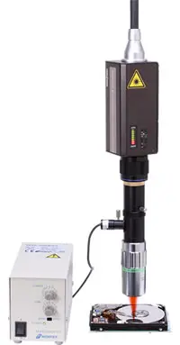
Mounting the LV-0181 (built-in positioning camera), the LV-0185 (illumination unit) and an objective lens to the LV-1800 enables micro spotting of laser beams and image observation by epi-illumination. It makes laser positioning to microstructures and detection of multipoint parts possible.
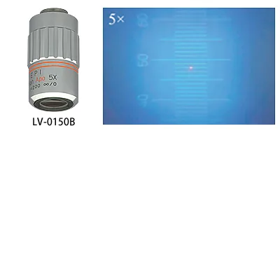 Objective lens LV-0150B
Magnification : 5x
WD : 36.1 mm
Spot diameter : φ4 μm or less
* A conversion adapter is provided as standard
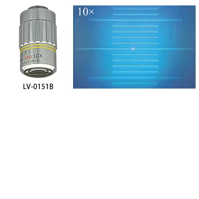 Objective lens LV-0151B
Magnification : 10x
WD : 38.8 mm
Spot diameter : φ3 μm or less
* A conversion adapter is provided as standard
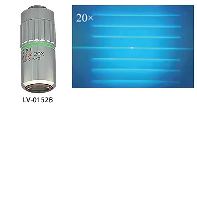 Objective lens LV-0152B
Magnification : 20x
WD : 22.5 mm
Spot diameter : φ2.5 μm or less
* A conversion adapter is provided as standard
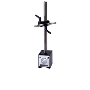 Magnet stand LV-0030
The magnet stand is used for sensor positioning. Laser can be irradiated with high angular flexibility with cross clamp. Using it together with the LV-0015 or LV-0016 fine-positioning stage enables fine adjustment of the detecting position.
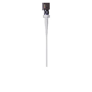
 Needle type beam bending mirror LV-0105
This mirror has φ4 mm of rod tip diameter, useful for the guide of detection at narrower space. Used by attaching to the tip of the
90-degree beam bending mirror LV-0301.
Tip of the rod diameter:φ=4 mm
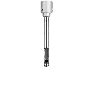
 90-degree beam bending mirror LV-0301
Attaching the mirror to the LV-1800 lens enables the laser beams path to bend
by 90- degree and rotated 360- degree, so that it can be aimed at small crevices such as behind the chassis.
ip of the rod diameter : φ=10 mm
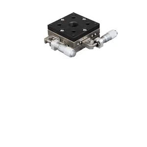 Fine-positioning XY stage LV-0015
The XY stage enables precise alignment of the sensor position. Using it together with the LV-0030 magnet stand, fine adjustment in X and Y directions can be performed. Using as a standalone unit, positioning of samples can be performed.
Stage surface:60 x 60 mm
Movable range: ±6.5 mm
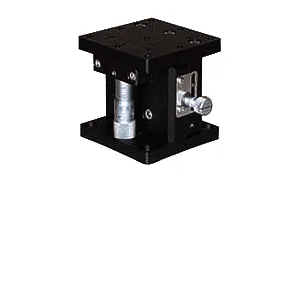 Fine-positioning Z stage LV-0016
The Z stage enables fine alignment of the sensor up/down position.
Using it together with the LV-0030 magnet stand, you can easily perform focusing of laser beams and image, and fine adjustment.
Stage surface:60 x 60 mm
Movable range:0 to 13 mm
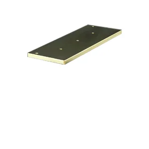 Steel plate LV-0018A
You can use this plate as a base on the LV-0030 magnet stand by mounting on the LV-0017A tripod. Fixing the LV-0015/0016 fine-positioning stage directly with screws prevents the stage and sensor from falling.
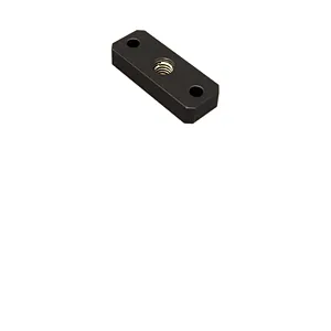 Camera screw adapter LV-0019
The adapter for mounting the sensor of the LV-1800 to the platform of the tripod LV-0017A (1/4-inch screw).
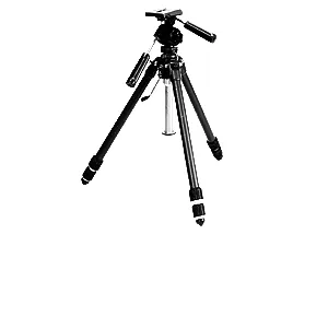 Tripod
Use this tripod to mount a sensor or a stand in a location without surface plate. Better use with the LV-0019 camera screw adapter (for direct mounting of a sensor to the tripod) and the LV-0018A steel plate.
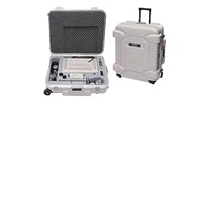 Storage trunk LV-0350
This storage trunk can store the LV-1800 main unit and other optional products together.
・LV-1800 x 1 /
・LV-0030(+LV-0015/0016) x1 /
・Objective lens x 2 /
・LV-0185 x 1 /
・LV-0018A x 1
Related information
Revised:2022/10/17