High-speed F/V Converter FV-1500
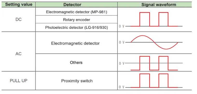
When inputting a pulse signal (negative voltage) centered around 0 V, recommend you to set the input signal type to AC.
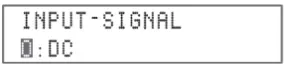
- SIGNAL: Input singal type
- Press the MENU button to start the setting mode. Then, expand 0: INPUT > INPUT-SIGNAL to show the input signal condition setting item.
Last updated:2024/05/28
In the setting mode, set the input signal format to PULL UP.
Operation procedure
1. In the measurement mode, press and hold [MENU] key to move to the setting mode.
2. With [∧]/[∨] key, select [MENU 0:INPUT] and press [SET/NEXT].
3. With [∧]/[∨]key, select [INPUT-SIGNAL 3:PULL UP] and press [SET/NEXT].
4. By pressing [MENU] key, you will go back to the measurement mode.
Last updated:2018/07/17
The response of output signal of the FV-1500 is one cycle +3.5µs of the input frequency.
When the input frequency range is 0.2 Hz to 320 kHz and input signal is 0.2 Hz, the output update time is approx. 5 seconds.
When there is no input signal, voltage value and current value of the output signal are held. If you do not set the stop time of the FV-1500, the output signal will become 0V after 5.5 seconds. (It becomes 0 mA or 4 mA when current is outputted.)
Last updated:2017/08/02
- Is it possible to reset the FV-1500 to the factory default settings? (settings at the time of factory shipment)
Hold [Menu] + [SET/NEXT] and power ON
[MEMORY ALL CLR? ] → [Y : SET/NEXT N : MENU]
Select "SET/NEXT" to start reset
- Reset of 10 setup conditions (Calibration values will not be cleared.)
Hold [<] + [SET/NEXT] and power ON
[ PANEL COND ALL CLR?] → [Y : SET/NEXT N : MENU]
Select [SET/NEXT] to start reset.
*Condition: This term is used to refer to "setup condition" in exclusive instruction manual. There are 10 memories to be used. Memory which is not "a condition" means each setting values.
Last updated:2014/06/17
High-Speed F/V Converter FV-1400 Discontinued
If an input signal suddenly stops, the FV-1400 outputs at 0V from 1 second after the input signal stops. (Except when the moving average function is in use.)
The output voltage depends on the interval (period) of the input signal. If the input signal suddenly stops, the FV-1400 waits the signal to come for 1 second. However, when there is no input signal for more than 1 second, the output voltage becomes automatically 0V.
Last updated:2011/09/20
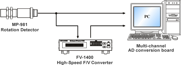
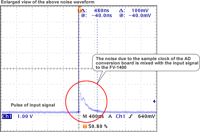
When you connect the input signal and output signal of the FV-1400 to the AD conversion board of a PC, noises from the sample clock of the AD conversion board may be mixed with these signals. Following diagrams are examples of the noise waveforms of the input signal and the output voltage signal.
Noise waveforms of the analog signals of the FV-1400
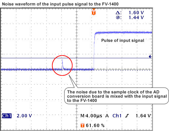
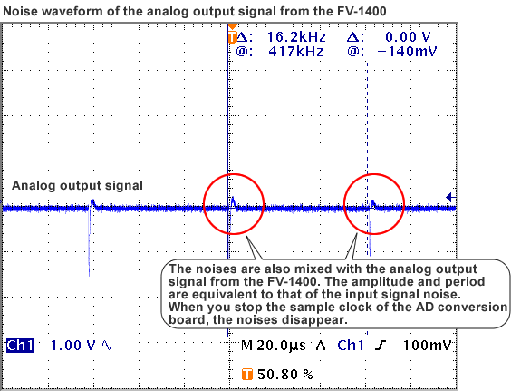
Even though you connect only the output signal from the FV-1400 to the AD conversion board, the noises due to the sample clock may be mixed with the output voltage signal, and moreover may travel to the input signal. In case of setting the input coupling of the FV-1400 to "AC coupling", an accurate measurement may not be performed due to the malfunction caused by the noises mixed with the input signal.
Please try these countermeasures as follows. In above example cases, the problem was solved by doing both of (1) and (2).
-
(1) If possible, the signal from the sensor should be inputted through an amplifier; that is, use "rectangular wave signal" such as the output signal of the MP-981 Rotation Detector. Moreover, set the input coupling of the FV-1400 to "DC coupling".
-
(2) Adjust the trigger level of the FV-1400 in order not to pick up the noises.
-
(3) Inquire the noise countermeasure from the manufacturer of the AD conversion board.
-
(4) Add a filter circuit (an isolation amplifier, etc.) and transmit the output voltage signal or the input signal of the FV-1400 through it, which prevents the noises due to the sample clock from traveling to the input signal. The filter circuit is to be supplied by our customers.
Last updated:2002/02/15
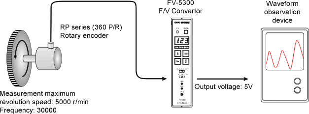
F/V Converter unit FV-5300 Discontinued
The settings and the meanings of input range, output range, factor, and monitor display are as follows.
| Input range | Set the maximum value to be measured (maximum value of the monitor display) For instance, set a maximum measuring values such as 500 r/min and 100 m/min. |
|---|---|
| Output range | Set the maximum values of output voltages and output currents with % Voltage: 0 to 10 V/0 to 100% Current output (optional): 0 to 16 mA/0 to 100 % or 4 mA to 20 mA/0 to 100% |
| Factor | Coefficient for unit conversion. Use this information for converting a frequency to a unit of revolution (r/min) or speed (m/min). |
| Monitor display | The value converted by dividing a frequency of an input signal by a factor is displayed. |
The following formula can be established.
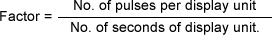 |
(1) |
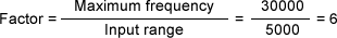
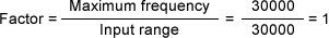
The factor can be obtained from the following formula.
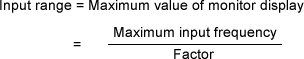 |
(2) |
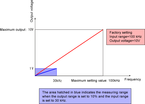
The following diagram shows the relationship between input frequency and output voltage.
|
Example 1: Setting the input range in the unit of revolution speed <r/min>.
| Measurement condition | Setting value |
|---|---|
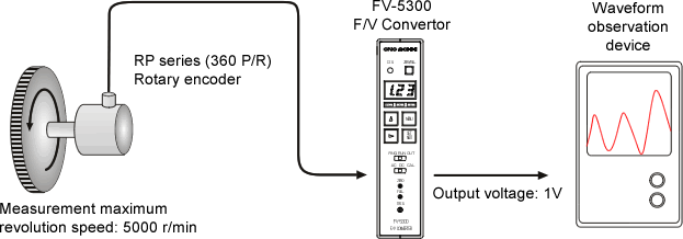
| RP series Rotary Encoder: 360 P/R Maximum revolution speed for measurement: 500 r/min Output voltage: 0 to 1V/0 to 5000 r/min Setting the input range in revolution r/min |
Input range: 5.00k Factor: 6 Output range: 10% Measuring range: Monitor display 0 to 5.00k |
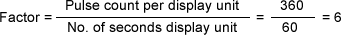
1. How to use formula (1)
Factor
Obtain the factor from formula (1). The display units will be r (1 revolution) and min (minute) based on the measuring unit r/min. Based on the settings of pulse count per 1r=360 and number of seconds for display unit: 1 min=60s, the following formula is established.
 |
Monitor display
Based on the setting of factor=6, the monitor display value is displayed in the unit of r/min automatically. 3-digit value is displayed. Use the information as a simple monitor.
 |
Input range
Although the maximum measuring revolution is 5000 based on the condition,
set 5.00k (k=factor of 1000) since the value comprises 3 digits.
When a signal exceeding this setting value is input, Input Over occurs.
In this case, it is necessary to review the condition such as increase of the input range setting value.
A limit is set for the input range setting and when the setting exceeds the limit, an error message is displayed.
Refer to "5.1 Input range" of the Instruction Manual for the details.
Output range
Set a maximum output voltage for the output range. This function limits the maximum output voltage up to 1 V when a device of the connection destination such as a recorder applies 1 V input. Refer to the "Setting value" column of the table provided above for the summary of the values that are obtained.
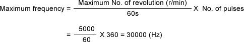
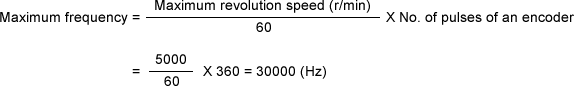
2. How to use formula (2)
Based on maximum revolution for measurement=5000 r/min and pulse count of the rotary encoder= 360 P/R:
 |
Based on the measurement condition, input range=5000 and as a result of conversion of formula (3), the factor is:
 |
The output range is the same as for item 1.
Example 2: Set an input range with frequency <Hz>
| Measurement condition | Setting value |
|---|---|
RP series Rotary Encoder: 360 P/R |
Input range: 30.0k (30,000) Factor: 1 Output range: 50% Measuring range: Monitor display 0 to 30.0k |
-
Obtain the maximum frequency using the method 2 in Example 1. Based on the maximum revolution 5000 r/min;
 |
-
Since the input range is set to the maximum frequency 30000, the factor is;
 |
-
Based on the measurement condition of 5 V, set the output range to 50%.
Refer to the "Setting value" column in the table shown above for the values that were obtained.
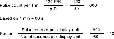
Example 3: Set an input range in speed (m/min).
| Measurement condition | Setting value |
|---|---|
RP-721 roller encoder: 120 P/R |
Input range: 100 Factor: 10 Output range: 100% Measuring range: Monitor display 0 to 100 |
-
Based on the specification of PR-721 in the measuring unit m/min;
 |
-
Based on the maximum speed for measurement 100 m/min, set the input range to 100. When a signal exceeding this setting value is input, Input Over occurs. In this case, the setting needs to be reviewed.
-
Since the output voltage is 10 V based on the output condition, set 100%. Refer to the "Setting value" column of the table indicated above for the values that were obtained.
Last updated:2011/09/20
FV Converter FV-1100 Discontinued
The standard specification of the FV-1100 Converter is maximum 10 kHz.
When the operating frequency is less than a half of the frequency range, the output voltage grows smaller and the ripple becomes larger. In above situation, the accuracy of the operating range becomes poor. We recommend you to modify the frequently used frequency range close to the full scale frequency.
(Example)
-
The accuracy for 10 kHz range: ± 0.2 % → 20 mV/ 10 V full scale/ 10 kHz full scale
-
-
When the operating range is 1 kHz or less: 1 kHz = 1 V, the accuracy for 1 kHz → 20 mV ÷ 1 V= 2 %/ 1 V/ 1 kHz
-
-
When change 1 kHz into full scale → 0.2 %/ 10 V full scale/ 1 kHz Full scale
Please consider the operating range of the FV converter to be 10 % to 100 % range of the full scale frequency (frequency range) as a rough guide.
Last updated:2002/02/15
High-response Frequency-to-Voltage Converter FV-1300 Discontinued
The approximate resolution of the FV Converter is shown in following diagram.
| Input frequency | Standard resolution |
|---|---|
| 10 kHz | 5 Hz |
| 1000 Hz | 0.05 Hz |
| 100 Hz | 0.007 Hz |
When the input frequency is 1500 Hz
The clock frequency of the cycle measurement is 20 MHz. The count value of the input frequency can be measured by the following formula;
20000000 ÷ (Input frequency) = Count value
With the input frequency of 1500 Hz: 20000000 ÷ 1500 = 13333.33
The count value is integer, so the resolution of the above formula is 13333 or 13334. By back calculating the count values into the frequency, following values are obtained.
20000000÷13333=1500.0375
20000000÷13334=1499.925
The difference between above formulas is 1500.0375−1499.925=0.1125 Hz
Due to this, it has approx. 0.12 Hz resolution in the input frequency of around 1500 Hz. Note that an error of 0.0375 Hz is occurred to the 1500 Hz measurement. With the consideration of the crystal oscillator accuracy, the 1500 Hz accuracy will be something over 0.12 Hz.
In the case of deviation output
In the case of deviation output, the resolution is same as the others, but the output voltage per one resolution is larger than others.
The accuracy of the voltage output of the low frequency
Outputs the voltage to which the inverse number of count value is converted by the 16-bit converter
When 1 is entered to each of 16-bit (full) of the binary counter, the frequency is 305.1 Hz.
When the frequency is 305.1 Hz or less, it becomes 16 bit or more. Cut off the lower bit of the binary counter and calculate by upper 16 bits.
The accuracy in this state is;
Accuracy = input frequency ÷ 215
The accuracy mentioned in the brochure
Voltage output 0.1 % FS
Current output 0.7 % FS
The resolution and analog circuit accuracy of 20 kHz are mentioned in the brochure because the accuracy of them becomes worst.
The input frequency can be modified to the maximum of
50 kHz. The accuracy of this model has same features as the other input
frequency.
Last updated:2011/09/20
Others
When you detect rotations using photoelectric detectors such as the LG-916 and the LG-930 with a piece of reflective mark on a rotating shaft, if the rotational speed is low, the number of pulses per second in a signal will be small. As a result, the output voltage will be as the questions above because the frequency of the signal will be extremely low among the frequency range of the FV conversion circuit.
Description
The TM-2130 and the FV-1100 utilize a FV conversion circuit (frequency-to-voltage conversion circuit) for converting an input signal into a voltage in proportional to the frequency of the signal.
A block diagram of the FV conversion circuit is as follows.
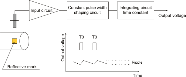
An integrating circuit is charged when the frequency of input pulses is high, and discharged when it is low. If the frequency of the input pulses becomes higher, the number of charging times increase and the charging time in total becomes longer; therefore the output voltage increases. To the contrary, when the frequency becomes lower, the discharging time will be longer than the charging time and the output voltage decreases. The smaller the time constant is, the faster the time of charge-discharge becomes and the wider the gap of charge-discharge voltage per 1 pulse (ripple) becomes. Also, the ripple is very small when the input frequency is high, however, the lower the frequency is, the larger the ripple becomes.
The photoelectric detectors such as the LG-916 and the LG-930 output same number of signals as the reflective marks attached on the rotating shaft per 1 rotation. Therefore, the input frequency tends to be low and the output voltage tends to be as mentioned in the question. You should calculate an input frequency from the range of rotation number which you would like to detect, and confirm that it will be more than 10% of the frequency range of the FV conversion circuit.
Follows are an excerpt of the quantity of the output voltage ripple at the input frequency is 1% of the frequency range. The whole table is in the TM-2130 instruction manual.
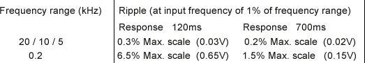
Last updated:2009/07/21