High-speed F/V Converter
FV-1500
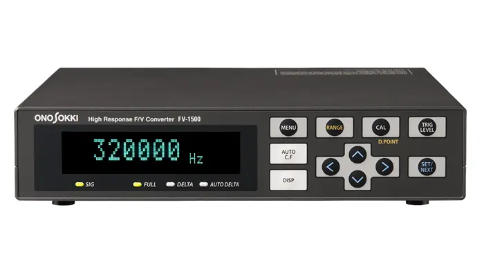

FV-1500 High-speed F/V Converter is a frequency-to-voltage
(current) converter that converts frequency signal
proportional to rotation speed, moving speed, etc. into
voltage signal.
The FV-1500 is designed to accommodate the needs of
high speed rotation measurement including rotating
motors used in HV/EHV production lines etc. It also
contributes to measure rising characteristics, very
small fluctuation in steady rotation, and transient
phenomena of flow speed with fast response.
Features
- Wide frequency range : 0.2 Hz to 320 kHz
- High-speed response : 1 cycle + 3.5 µs
- Rapid deceleration follow-up function enables practical signal output even when the frequency brings about a sharp drop.
- Automatic center frequency follow-up function can close up transient fluctuation component (option).
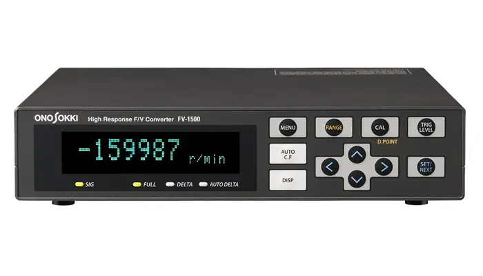
- Provided forward/reverse output by rotation direction recognition using two-phase signal input.
- Comparator output useful for alarm system(option)
Typical applications
Rising characteristics of motor
Rotation performance of rotating devices
Rotation fluctuation measurement of engines or motors
Rotation performance test by applying excessive load
What is Rapid deceleration follow-up function (Estimating calculation function) ?
Output signal (speed analog) results in gradual reduction to stop when succeeding input signal of rotating device is suddenly decreased. The pulse interval is calculated every signal input. If no-signal period lasts longer than the previous pulse interval, this function enables the rotation output to be in gradual decline.
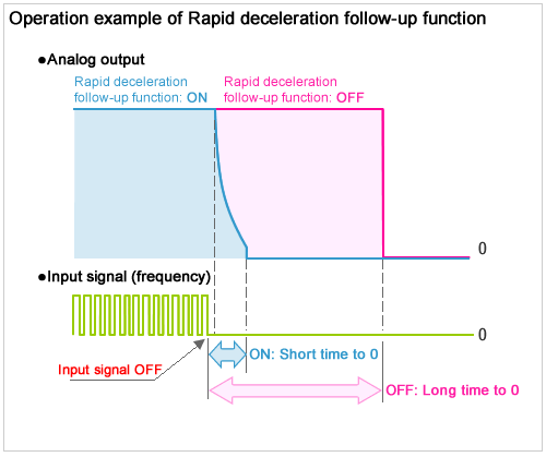
Follow-up function
ON
Analog output will be 0 when the no-signal
period lasts longer than 1.5 to 16 times of the last signal
pulse interval.
Follow-up function
OFF
Analog output will be 0 after that the
minimum measurement frequency (0.2 Hz) is retained from the
time input signal is 0 (OFF) for a while.
Overview specification
Input specification |
|||||||||
|---|---|---|---|---|---|---|---|---|---|
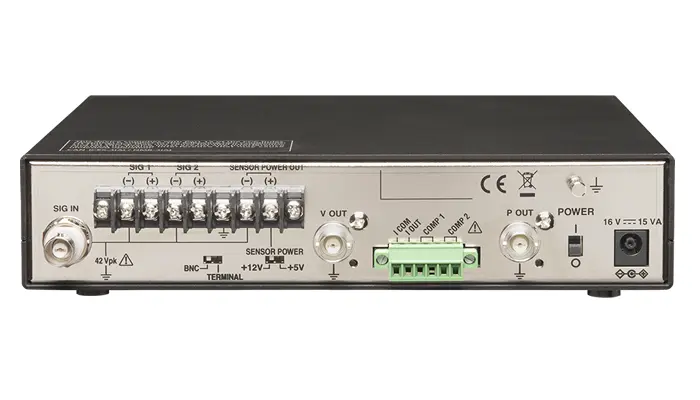
| Input connector | BNC(C02 type), terminal block | ||||||||
| Input format | Single-phase, AC/DC/non-voltage selectable(+12 V pull-up for
open collector devices) Two-phase signal with 90° phase difference(DC input only) |
||||||||
| Input voltage | AC input signal voltage range :0.3 Vp-p to 30 Vp-p | ||||||||
| DC input signal voltage range :Lo;+1 V or less, Hi;+4 to 30 V | |||||||||
| Filter | OFF / 20 kHz / 120 kHz low-pass filter | ||||||||
| Input impedance | 2.2 kΩ | ||||||||
| AC coupling frequency | 0.9 Hz approx. -3 dB | ||||||||
| Minimum input pulse width | 1.5 µs | ||||||||
| Input signal detection edge | Rising / falling selectable | ||||||||
| Input frequency range | 0.2 Hz to 320 kHz
|
||||||||
Signal output specification |
|||||||||
Analog output signal |
|||||||||
| Analog output connector | BNC/C02 type(voltage output)or terminal block (phoenix contact:MC1,5/6-STF-3,81)(voltage output)selectable | ||||||||
| Conversion time | 1 cycle +3.5 µs or less | ||||||||
| D/A resolution | 16-bit | ||||||||
| Filter | OFF / 3 Hz / 10 Hz / 1 kHz selectable, low-pass filter | ||||||||
| Analog output connector signal |
|
||||||||
| Output DC offset | Voltage output:± 10 mV or less | ||||||||
| Current output:± 0.01 mA or less | |||||||||
| Temperature coefficient | Voltage output:± 0.02 % FS/°C | ||||||||
| Current output:± 0.07 % FS/°C | |||||||||
| Output impedance | 50 Ω or more(voltage output) | ||||||||
| Load resisntance | Voltage output:100 kΩ or more | ||||||||
| Current output:500 Ω or less | |||||||||
| Linearity (For full scale mode) |
|
||||||||
Pulse output signal |
|||||||||
| Pulse output | BNC(C02 type) Output connector voltage: Lo: +1 V or less, Hi:+4.5 V or more Load resistance:100 kΩ or more |
||||||||
| Pulse output (option: FV-0154) | Open collector output Withstand voltage:DC30 V, sink current:50mA or less |
||||||||
Comparator output signal(option: FV-0152) |
|||||||||
| Comparator output terminal | Terminal block (phoenix contact MC1,5/6-STF-3,81) | ||||||||
| Output format | Semiconductor relay (one make contact) 2ch | ||||||||
| Maximum contact capacity | DC 30 V/1 A | ||||||||
| Contact ON resistance | 25 Ω or less | ||||||||
| Setup | UPPER, LOWER Relay ON: UPPER setup value ≤ measurement value Relay ON: LOWER setup value > measurement value |
||||||||
| Other functions (provided as standard) |
Delay function | The delay function performs comparator output when the set value is consecutively exceeded the preset number of times. Can be set in the range from OFF (0) to 100 times. | |||||||
| Hysteresis function | Return values of frequency, rotation speed or moving speed can be set in the range from 0 % to 20 % in increments of 1 %. | ||||||||
| Hold function | This function sets the minimum output time to keep contact ON status in the range from 1 to 1000 ms, in increments of 1 ms. | ||||||||
Function |
|||||||||
| Moving average | OFF / simple moving average 2 to 720 times / exponential moving average 2 to 64 times | ||||||||
| Number of pulses | 1 to 999999 P/R | ||||||||
| Factor | 0.0001 to 99999 | ||||||||
| Multiplying / dividing | Multiplying:OFF / 2 / 4 (only when two-phase signal with 90° phase difference) frequency dividing: OFF, 2 to 1000 | ||||||||
| Condition memory | Can be stored up to 10 types of conditions. | ||||||||
| Rapid deceleration follow-up function(Estimating calculation) | OFF / TYPE1 / TYPE2 | ||||||||
| Stop estimating calculation time | OFF / NUM:1.5 times to 16 times / TIME:1 ms to 4000 ms | ||||||||
| Direction recognition | OFF / ON (only when two-phase signal with 90° phase difference) | ||||||||
| CAL | Voltage output ZERO : 0 V, FULL: 10 V | ||||||||
| Current output ZERO : 0 mA (4 mA), FULL:16 mA (20 mA) | |||||||||
Display |
|||||||||
| Display accuracy | displayed value* x (±0.01%) ± 1 count or less (* Count value : The value that a decimal point is ignored. ) |
||||||||
| Display | Fluorescent display tube (display range 69.85 mm × 11.45 mm) Selectable from four brightness degrees |
||||||||
| Display update time | 0.5s, 1s | ||||||||
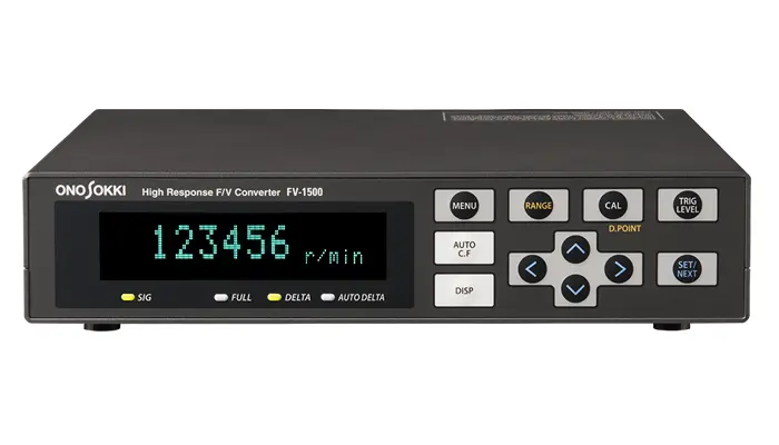
| Display unit | Hz, r/min, m/min, USER | ||||||||
| Status LED display | SIG | Flashes each time a signal is input | |||||||
| Measurement mode | Full scale, deviation, automatic center frequency follow-up function(option: FV-0151) | ||||||||
Sensor power |
|||||||||
| Sensor power | +12 V±1 % 150 mA / +5 V±10 % 150 mA Selectable by SENSOR/POWER switch on the real panel. |
||||||||
Conforming standard |
|||||||||
| CE marking | Low Voltage Directive 2006/95/EC EN61010-1:2010 | ||||||||
| EMC Directive 2004/108/EC EN61326-1:2006 Class A Table 2 | |||||||||
General specification |
|||||||||
| I/O ground | Signal ground of V OUT and I OUT are in common. Signal ground of SIG IN, SIG 1, SIG 2 and sensor power (+12V, +5V) are in common. The signal input and sensor power ground shall be isolated from the chassis. The input and output grounds shall be isolated from each other. The withstand voltage between the isolated signal grounds and between chassis shall be up to 42 Vpk. |
||||||||
| Power requirement | 16 VCD ±10 % Exclusive AC adapter (100 to 240 VAC) |
||||||||
| Power consumption | Approx. 36 VA or less | ||||||||
| Operating temperature range | 0 to 40 °C | ||||||||
| Storage temperature range | -10 to 50 °C | ||||||||
| Operating humidity range | 5 to 80 %(with no condensation) | ||||||||
| Storage humidity range | 5 to 85 %(with no condensation) | ||||||||
| Outer dimensions | 210(W)×44(D)×200(D) mm(excluding protruded section) | ||||||||
| weight | Approx. 1 kg | ||||||||
| Accessory | Exclusive AC adaptor (PS-P20023 / VM1391-VM1700 2m) X 1, instruction manual X 1, connector (MC1.5/6-STF-3.81) X 1 | ||||||||
Option |
|||||||||
| Option | FV-0151: Automatic center frequency follow-up function FV-0152: Comparator output function FV-0153: Deviation scale change function(±10 V) FV-0154: Open collector output function(pulse output) FV-0014: Panel mounting fixture |
||||||||
*When measuring the moving speed (m/min) with the combination of the RP-7400 1200 P/R, set the display unit to "USER".
Related information
Revised:2020/10/21