
![]()
![]()
![]()
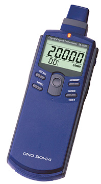
Gasoline Engine Tachometer
SE-2500
Both analogue (which can be switched over to monitor also) and pulse output function are provided as standard. Analogue output signal can be used for the recording the signal from data recorder and so on. Monitoring output signal can be used for checking the sensors detection waveform or as the input signal by FFT analyzer. Pulse output signal can be used as external clock signal for tracking analysis by FFT analyzer.
IP-2800 External Sensor (Accessory)
Featute
Built-in memory function 20 data (MAX) can be saved to memory.
Three outputsanalog, monitor and pulseprovided as standard
Large LCD with backlight
Capable of performing measurement at a distance of 1 m when the external sensor (IP-2800) is used.*
Can be mounted on a tripod
Measurement can be performed in 1 r/min or 0.01 r/s units.
*Measurement is impossible depending on the type of the engine.
Measurement method
 |
 |
Specifications Summary
| Applicable engines | Gasoline engines 2-cycle (1, 2, 3, 4 cylinders), 4-cycle (1, 2, 3, 4, 5, 6, 7, 8, 10, 12 cylinders) |
||||||||||||||||||||||||||||||
|---|---|---|---|---|---|---|---|---|---|---|---|---|---|---|---|---|---|---|---|---|---|---|---|---|---|---|---|---|---|---|---|
| Detection method | Electromagnetic induction | ||||||||||||||||||||||||||||||
| Detection distance | 10 to 200 mm | ||||||||||||||||||||||||||||||
| Object of measurement | Ignition coil | ||||||||||||||||||||||||||||||
| Calculation method | Cycle calculation method | ||||||||||||||||||||||||||||||
| Measurement time | Within 1 s + the time required for one cycle | ||||||||||||||||||||||||||||||
| Display | 5-digit LCD, with backlight (character height: 10.2 mm) | ||||||||||||||||||||||||||||||
| Display update time | 1 ±0.2 s | ||||||||||||||||||||||||||||||
| Measurement units | r/min, r/s | ||||||||||||||||||||||||||||||
| Measurement ranges |
|
||||||||||||||||||||||||||||||
| Measurement accuracy | Displayed value* x (±0.02%)
±1 count * The displayed value is the count value excluding figures after the decimal point. |
||||||||||||||||||||||||||||||
| Memory function | 20 data (MAX) | ||||||||||||||||||||||||||||||
| Over-range function | The over-range alarm (ERROR mark) is displayed when the measured value exceeds the display range. | ||||||||||||||||||||||||||||||
| Rotation upper limit alarm function | The upper limit alarm ( mark) is displayed when the number of rotations exceeds the preset upper limit value. | ||||||||||||||||||||||||||||||
| Sensitivity adjustment function | A rotary dial at the right-hand side of the device is used to adjust the sensitivity. | ||||||||||||||||||||||||||||||
| Analog output | Output with respect to the
displayed rotation values
Output voltage: 0 to 1 V/0 to FS
(FS is freely selectable) |
||||||||||||||||||||||||||||||
| Monitor output | Analog output for monitoring purposes after waveform
reshaping of the sensor signal
Load resistance: At least 100 kΩ |
||||||||||||||||||||||||||||||
| Pulse output | 1 pulse output per signal
detection
Output voltage: Hi level: At least +4.5, Lo level: Up to
+0.5 V |
||||||||||||||||||||||||||||||
| Power source | Four AAA alkaline batteries or exclusive AC adapter (PB-7090, Option) | ||||||||||||||||||||||||||||||
| Battery life | At least 32 hours (when the
backlight is OFF) At least 8 hours (when the backlight is ON) |
||||||||||||||||||||||||||||||
| Low battery alarm indicator | A low battery alarm (LOW mark) is displayed when the battery voltage falls below 4.4 V. | ||||||||||||||||||||||||||||||
| Operating temperature range | 0 to 40°C | ||||||||||||||||||||||||||||||
| Storage temperature range | -10 to 50°C | ||||||||||||||||||||||||||||||
| Outer dimensions | 198.5 (W) x 47.5 (H) x 66 (D) mm | ||||||||||||||||||||||||||||||
| Weight | Approx. 300 g (including batteries) | ||||||||||||||||||||||||||||||
| Accessories | Ignition detector (IP-2800) , AAA alkaline batteries × 4, Carrying case |
Options
| LA-0203A Tripod | HT-0522/0521A Magnetic stand/Stand jig | PB-7090 AC adapter |
|---|---|---|
 |
 |
 |
Revised:2010/12/14