This product is discontinued /
Replaced by FT-7200 Advanced Handheld Tachometer (Click here)
  Ono Sokki Company, Ltd.

Discontinued
Replaced by
FT-7200 Advanced Handheld Tachometer

HOME > Products Information > Rpm & Speed > Advanced Tachometer FT-7100
Advanced Tachometer
FT-7100

Photo (FT-7100 Advanced Tachometer) The FT-7100 is a handheld tachometer that uses FFT calculations to perform frequency analysis and measure rotational speed. It can be used in a wide range of measurement applications, such as motor's constant and steady rotational speed and engine rotations during acceleration/deceleration etc.

New algorithms with FFT calculating function enables the non-contact measurement of the rotational speeds by sound or vibration from the object under measurement, which was impossible up to now.


Features

  • Rotation measurements can be taken even by sound or vibrations - no need for the modification or attachment to the rotational shaft for the measurement.

  • Capable of measurement even changes in rotational speed during acceleration or deceleration.

  • Effective for measuring the rotational speed of engines in completed vehicles.

  • Various sensors can be used.

  • Provided with an analog output function.

  • Large size LCD with backlight for displaying the measured result is provided.

  • Provided with an averaging function.


Measurement mode

Four measurement mode algorithms can be selected to suit your measurement application

Measurement mode Measurement algorithm
Constant rotation measurement (CNS) Maximum peak frequency method
Frequency interval method
Accelerated/decelerated rotation measurement (ACT) Maximum peak frequency method
Rotational speed candidate selection


Maximum peak frequency method


Calculation is performed using the frequency of the power spectrum's maximum peak. Measurement is normally performed in this mode.


Frequency interval method


The frequency intervals of the order components of the rotation are sought sequentially. The largest frequency interval is judged to be the first-order component of the rotational speed. This method is used to determine the rotational speed, and is an effective method to use when the first-order peak is unstable.


Rotational speed candidate selection


For the rotational speed measurement, the peak frequency of the arbitrary one power spectrum is observed among the max. eight power spectrum.


Rpm measurement
of the motor

Rpm measurement 
from vibration

Rpm measurement
from the magnetic leakage


Application examples

Using a microphone or an accelerometer to measure the rotational speed of an engine

The rotational speed of an engine can be measured by the sound or vibration caused by the movement of the pistons. This is an effective measurement method when the engine compartment is covered, and engine rotation sensors cannot be attached.

  • Set the number of pulses to match the number of ignition firings per one crankshaft rotation.
    Example: In the case of a four-cylinder engine with four-cycle, the number of pulse is set at 2 P/R.


Measuring the rotational speed of DC motors incorporated into home appliances

This example shows how to measure the rotational speed of DC motors that are built in the home appliances. Even if the DC motor has been installed deep inside an appliance such as an electric toothbrush, the rotational speed can be obtained by the magnetic flux leaking from the motor.

  • The rotational speed can be measured simply by inputting the number of poles in the DC motor rotor.


Using an engine rotation sensor to measure the rotational speed of an engine

The rotational speed of an engine can be measured by clamping a sensor to the primary low-voltage or secondary high-voltage conductor. Measurement can be performed simply by inputting the number of ignitions per rotation.

  • Set the number of pulses to match the number of ignition firings per one rotation.
    Example: In the case of a 4-cycle engine If you will be performing measurement on the primary conductor, set the number of pulses to half the number of cylinders. If you will be performing measurement on the secondary conductor, make the setting 0.5 P/R so that there is one pulse for every two rotations.


Using an accelerometer to measure the rotational speed of a small fan

This example shows how to measure the rotational speed of rotating objects such as a small fan. The vibrations from a rotating object depend on the rotational movement of that object. The rotational speed of an object can be obtained by measuring the vibration frequency.


Using an accelerometer to measure the rotational speed of a compressor

This example shows how to measure the rotational speed of the compressors that are used in air conditioners and similar equipment. When used in combination with an accelerometer, the FT-7100 can be used to measure the rotational speed of a compressor whose rotational shaft is not directly accessible.


Using a microphone to measure the rotational speed of an engine from the muffler noise

This example shows how to measure the rotational speed of an engine from an automobile's muffler noise. Since the pulsation component of the engine rotation is included in the muffler noise, the engine's rotational speed can be obtained by this pulsation frequency component.

  • Set the number of pulses to match the number of ignition firings per one crankshaft rotation. Please note, however, that depending on muffler performance, there may be cases when measurement cannot be performed.


Specifications

Compatible sensors
 
Engine rpm OM-1200、IP-292、IP-296、IP-3000A、IP-3100
Vibration VP-202、VP-1220、NP-2000 series、NP-3000 series
Sound Microphone:MI-1233, MI-1431
Microphone preamplifier:MI-3110

* Charge amplifier is required additionally when NP-2000 series accelerometer is used.

Voltage levels 5V  :Max ±5V
0.5V :Max ±0.5V
0.05V :Max ±0.05V
Input coupling AC coupling
Input Connector CO2(BNC)
Calculation method FFT calculation
Measurement time Within 250ms
Input frequency ranges 2000Hz range:30Hz to 2000Hz
500Hz  range:7.5Hz to 500Hz
250Hz  range:3.75Hz  to 250Hz
Measurement unit r/min (rotational speed)
Measurement accuracy

±2 x rotational speed resolution (r/min), ±1 count

* The rotational speed accuracy depends on the frequency range.

Minimum rotational speed resolution

Frequency range (Hz) ÷ 6400 x 60 ÷ the number of pulses set (P/R)

* The resolution becomes coarse when the rotational speed is accelerating or decelerating.
    6400 = 200 lines x 32

Filter function Limited to the frequency range that you wish to measure (rotational speed range) from the overall range of the selected frequency range
Averaging Moving average No. of averages: OFF, 2, 4, 8, 16
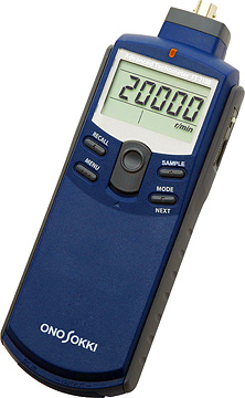
Sensor amplifier sensitivity adjustment dial The sensor amplifier sensitivity can be adjusted by using the rotary dial located on the right side of the main unit.
Power supply for the NP sensor Rated current power supply ±2.4 (0.5 mA)
Display 7-segment LCD, backlight, 5 digits, Character height:10.2 mm
Display update time 0.5 ± 0.2 s
Display resolution 1 r/min
Measurement modes
 
CNS(Constant) Use this mode when there are minimal fluctuations in the rotational speed of the object under measurement (when measuring the rated speed or similar)
ACT(Active) Use this mode when the rotational speed of the object under measurement accelerates or decelerates (please note, however, that measurement may not be performed correctly in the case of sudden changes)

[REVO] Analog output Signal output: In proportional to the rotational speed displayed value
Voltage range: 0 to 1 V/0 to F.S. (F.S. can be specified freely)
Conversion method: 10-bit D/A conversion
Linearity: ±1% of F.S.
Output refresh time: Within 250 ms
Temperature stability: ±0.05% of F.S./°C (ZERO & SPAN)
Setting error: ±0.5% of F.S. (adjustment setting error at the time of shipment from the factory, ZERO & SPAN)
Load resistance: At least 100 kΩ
Output connector: Ultra-mini jack (φ2.5)
[SIG] Analog output for the monitor Signal output: Analog output for the monitor after waveform shaping of the sensor signal
Load resistance: At least 100 kΩ
Output connector: Ultra-mini jack (φ2.5, same which is also used as REVO output.)
Power source Four AAA alkaline batteries or dedicated AC adapter (PB-7080, sold separately)
Continuous measurement time

Approx. 7 hours (when the backlight is off) Approx. 6 hours (when the backlight is on) (When alkaline batteries are used at a temperature of 20°C; excluding the use of an NP series accelerometer *1)

*1: When an NP series accelerometer is used, current consumption increases because of the constant current power supply used to drive the NP series accelerometer. Use of the dedicated adapter is therefore recommended.

Battery LOW display

The "LOW" mark flashes when the voltage has dropped to approx. 4.2 V
Operating temperature range 0 to +40°C
Storage temperature range -10 to +50°C
Operating humidity range 35 to 85% RH (non-condensing)
Storage humidity range 35 to 85% RH (non-condensing)
Outer dimensions 189.5 (L)  x 66.0 (W)  x 47.5 (D) mm (main unit only)
Weight Approx. 230 g (main unit only, batteries not included)


Options

Ignition pulse detector (Primary side) IP-292

Ignition pulse detector (Secondary side) IP-296

Engine rotation detector IP-3000A

Engine rotation detector
 IP-3100
IMotor/gasoline engine RPM detector
OM-1200

DC motor rotation detector
FT-0501

Engine vibration detector
VP-202

Engine vibration detector (High-sensitive type) VP-1220

Piezoelectric-type accelerometers
NP-2000/3000 Series

* Charge amplifier is required additionally when NP-2000 series accelerometer is used.

Microphone + preamplifier
MI Series

Magnetic stand/stand jig
HT-0522/0521A

The state which attached
the main body.

Tripod LA-0203C

AC adapter PB-7090

PB-7090

Analogue output signal cable AX-501

Charge converter
CH-6130/6140


Revised: 2010/12/14

Contact Us Questions and Inquireies (Feedback form) Back to previous page