GPS Speedometer LC-8300A UPDATED in Jul 2025
The lineup of GPS speedometers has been renewed. The LC-8300A is the flagship model developed by our company, a pioneer of speedometers.
Our original IMU correction algorithm enables stable speed measurement regardless of the test environment,
even in urban areas where radio interference is likely to occur due to trees and buildings.
Equipped with various functions for the test that complies with regulations,
it supports a wide range of vehicle test.
With a compact body design and a simple configuration, you can test without a PC.
It is useful for a variety of measurement needs.
New functions
Strengthening data governance
It enables you to quickly and clearly verify the authenticity of test results, while also contributing to greater efficiency in post-test evaluation tasks.
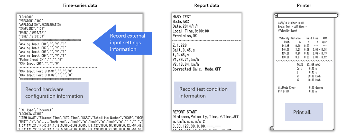
Output all settings
It can save and print all settings that affect measurement and calculation results.
Not only can you check the settings later, but also use it as a means of proving that the test results have not been manipulated arbitrarily.
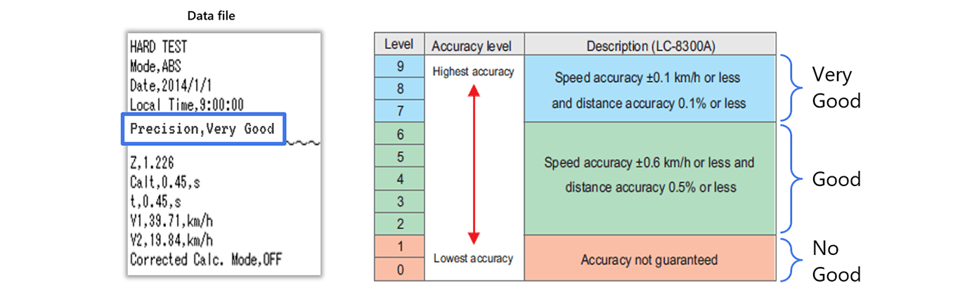
Recording the results of precision level judgment
This function records the results of precision level judgments within the data file.
It allows you to instantly check whether the measurement results meet the accuracy standards specified by various automotive test regulations.
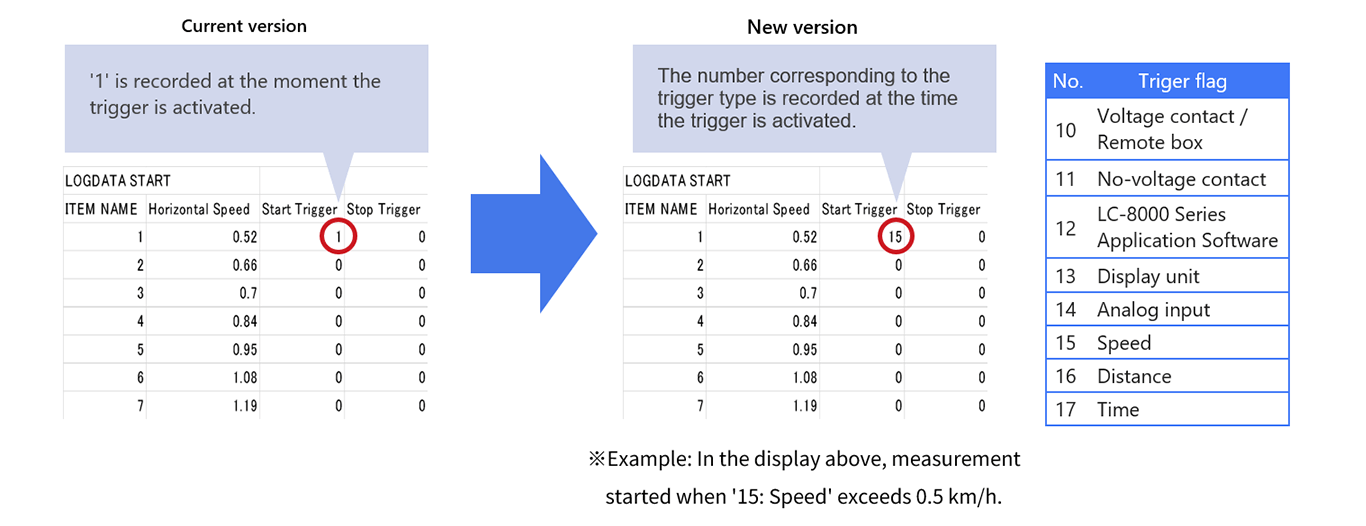
Recording the trigger type
This function records the trigger type in a data file.
You can check afterwards which trigger started and stopped the measurement. This clarifies that the test was performed correctly and increases the reliability of the results.
Enhancement of ABS test function
Required options:
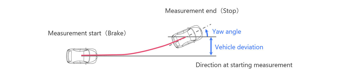
LC-0833 Orbit Display function
LC-0836 IMU data Output function
It enables to measure, display, and save the drifting value and the change in yaw angle (vehicle tilt angle).
In ABS testing, quantitative evaluation using measuring instruments rather than subjective visual judgement improves the authenticity and reproducibility of test results.
Improved operability
Pursuing ease of use, including operability and visibility
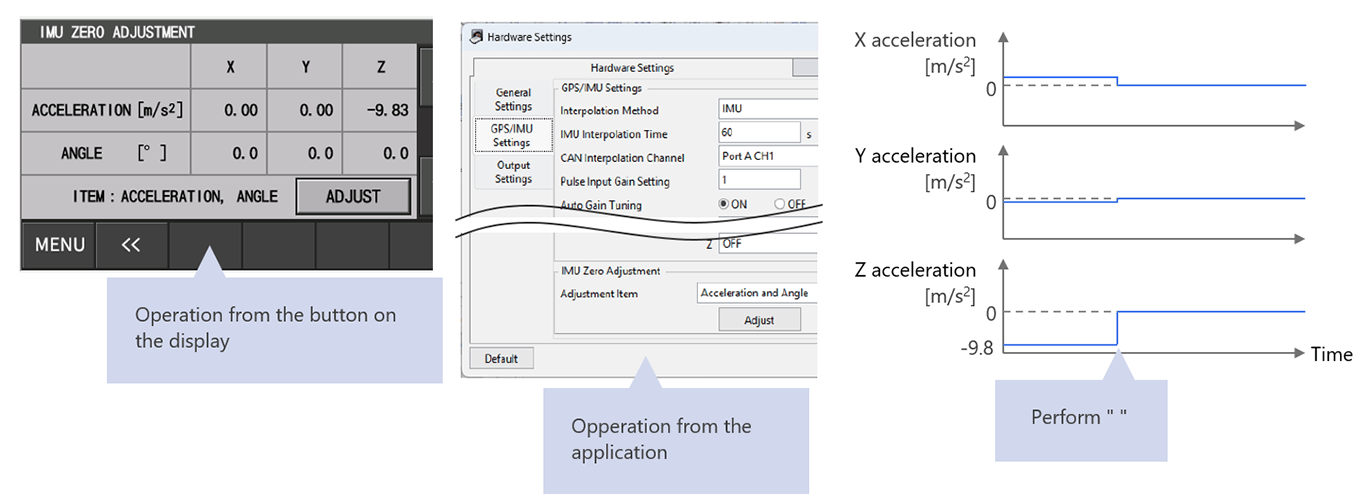
IMU Zero Adjustment
This function adjusts the acceleration values of the X/Y/Z axes and the roll, pitch, and yaw angles to zero. By operating the buttons on the display or app, you can set the current state as the zero point. This eliminates the need for post-processing to correct for gravitational acceleration (-9.8 m/s2) or misalignments caused by the IMU's tilt.
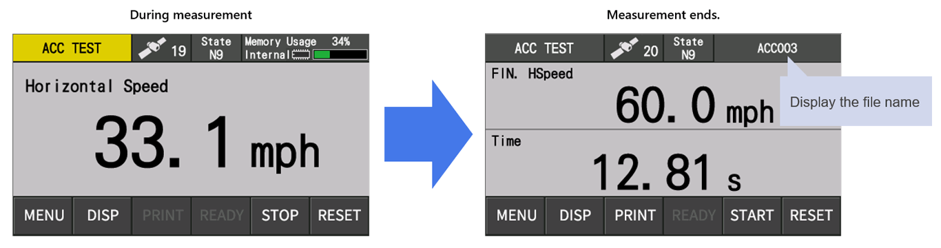
Indicates the file name on the display
The file name will be indicated when the measurement ends. It will become easier and more reliable to link data to driving data.
Expansion of data file loading size
The size of data files that can be loaded by the application software have significantly been expanded, which allows for smooth handling of long-duration measurement data such as on-road test.
(Previous version) 65,000 points (approximately 10 minutes and 50 seconds*) (New version) 500,000 points (approximately 83 minutes and 20 seconds*)
* Sampling frequency: 100 Hz
Renewal of optional functions
Orbit Display function (LC-0833)
New functions have been added that not only enhance the authenticity of the test, but also contribute to work efficiency and safety during the test.
Feature
Stable measurement
- Achieve outstanding stability
- Improved satellite acquisition performance
Adopts a highly sensitive GPS/GLONASS receiver that is four times more sensitive than existing models. As a result, the satellite acquisition performance has been greatly improved, and there is no need to worry about satellite acquisition being interrupted during measurement. Also, the antenna can be installed inside the vehicle.
- GPS supported by IMU correction
By using not only the velocity information from GPS but also correcting by IMU, stable measurement is realized even in environments where radio wave reception is unstable.
In addition, even if the satellite acquisition condition is good, the velocity correction is constantly performed by the IMU. Thus. it is possible to output speed data very accurately compared to using GPS alone.
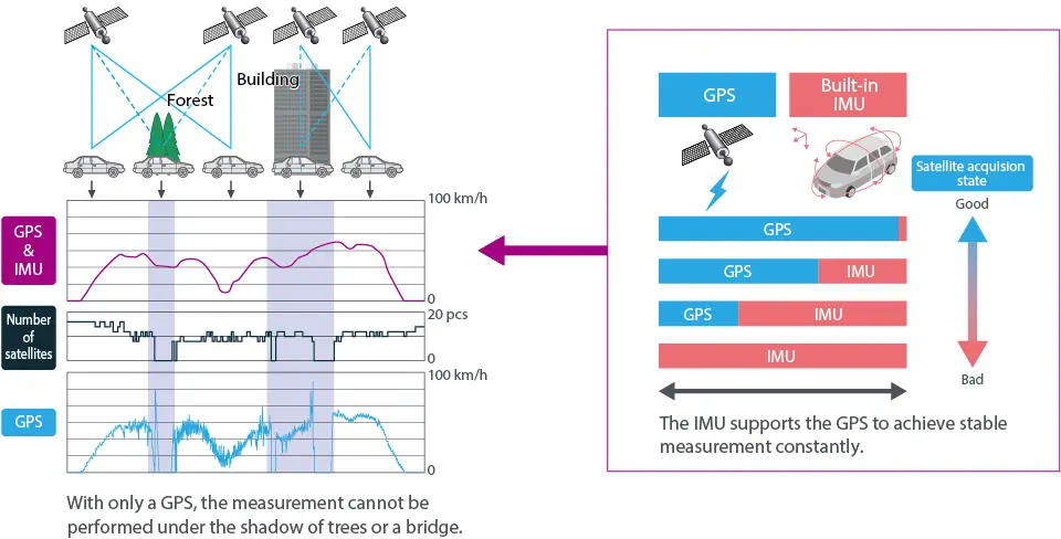
The above figure is an image of satellite acquisition and correction by IMU.
We do not guarantee the accuracy of our products or the number of satellites captured.
In addition, depending on the vehicle type and driving environment, the number of satellites captured may decrease and the measurement may become unstable.
- Expanding application scenes
- Expanding application scenes
Stable measurements can be performed without worrying about satellite loss, not only in open spaces such as test courses,
but also in urban areas where radio interference is likely to occur due to trees and buildings and under elevated roads.*
Also, when the vehicle is stopped, such as waiting at a traffic light, the speed display will stop at exactly 0 km/h.
* Depending on the driving environment, the number of satellites captured may decrease and the measurement may become unstable.
- For a wide range of test needs
The GPS antenna can be installed not only on the roof of the vehicle but also inside.* It can be used for a wide range of test needs, such as running resistance performance.
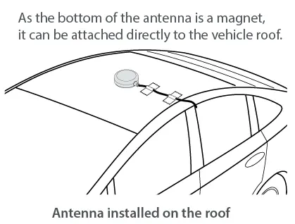
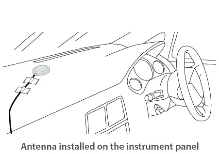
* Depending on the vehicle type and driving environment, the number of satellites captured may decrease and the measurement may become unstable.
For tests that require high distance accuracy and is sudden acceleration/deceleration, install the antenna on the roof.
- Perfect for such test scenes
Noise test
Not affected by wind noise
Coasting test
Air resistance does not increase
Actual driving test
Not conspicuous appearance
Test under bad weather*
Test in rain or snow
* The antenna has a protection class of IP67, thus it can be installed on the vehicle even in bad weather.
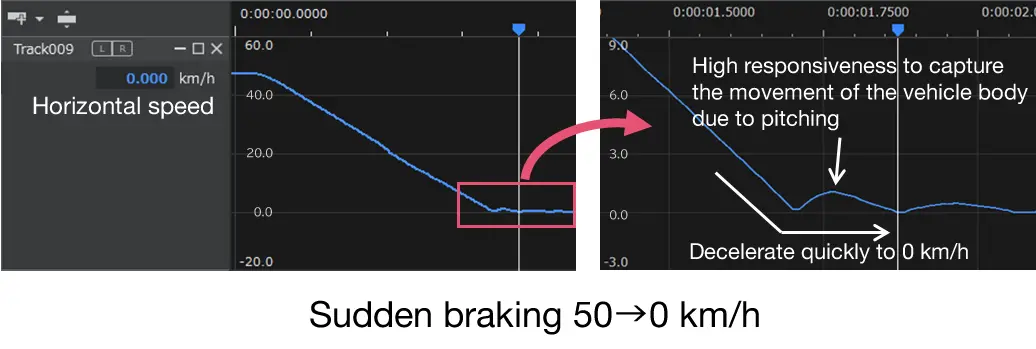
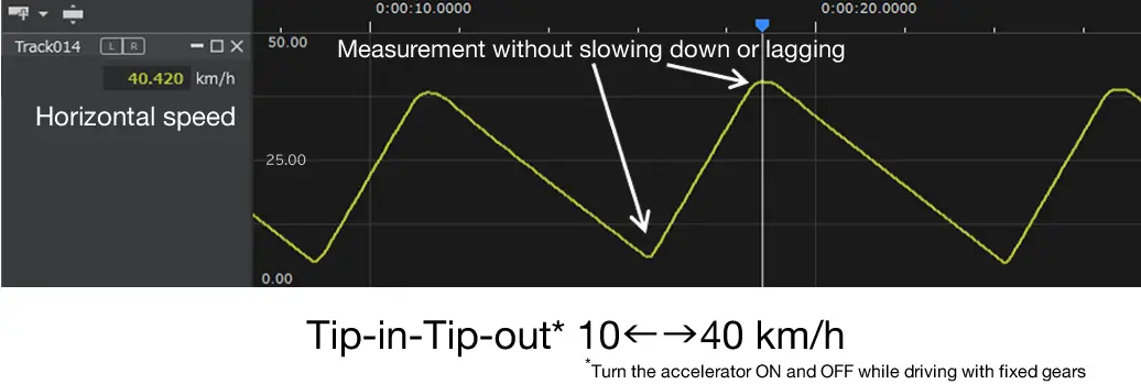
High response
- Even in sudden acceleration, sudden braking
High responsiveness is achieved by the correction function using IMU. Our original algorithm achieves both responsiveness, stability, and low noise. It is ideal for tests that require accuracy of transient response such as acceleration tests, braking tests, and steering stability.
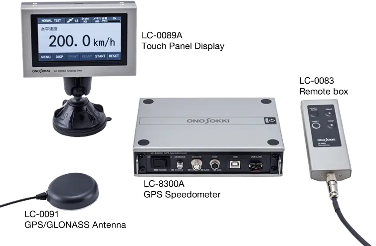
Compact designed for on-board measurement
- Useful for various test vehicles
Space saving of about 60% by volume compared to the LC-8120 and reduced wiring that the IMU is built-in. Equipped storage function in the main unit, internal storage of main unit, it is possible to test with a simple configuration consisting only of the main unit and peripheral devices (Standalone Test Mode, PC-less). It can be used not only for four-wheeled vehicles, but also for vehicles with limited installation space, such as motorcycle, agricultural machinery, and construction machinery.
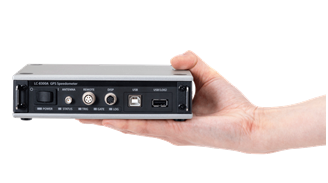
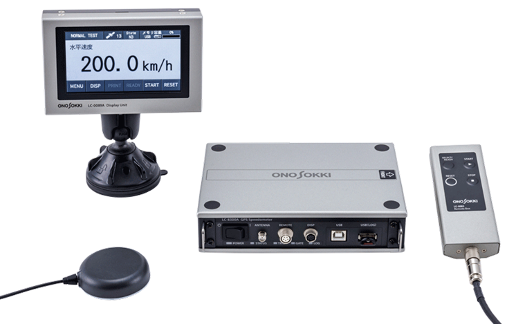
Palm size, compact and lightweight body
(LC-8300A GPS Speedometer)
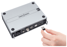
Test results are recorded in the internal storage of the main unit
or USB memory (Standalone test mode)
* When it is difficult to attach horizontally the LC-8300A to a vehicle, the external IMU (optional) connection is also available.
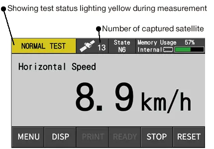
Touch panel display
- Easy-to-use design
The display installed in the car is a LCD touch panel type. It is easy to see while driving and user-friendly UI.
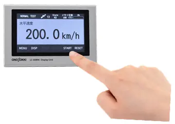
LC-0089A Touch panel display
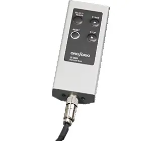
START, STOP, RESET be operated from either the touch panel or remote box
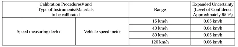
JCSS*1 calibration conforming to IATF 16949*2
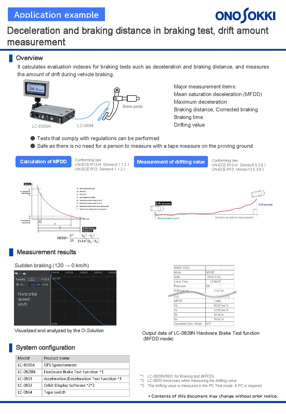
- Mean saturation deceleration (MFDD)
- Maximum deceleration
- Braking distance, Corrected braking
- Braking time
- Drifting value
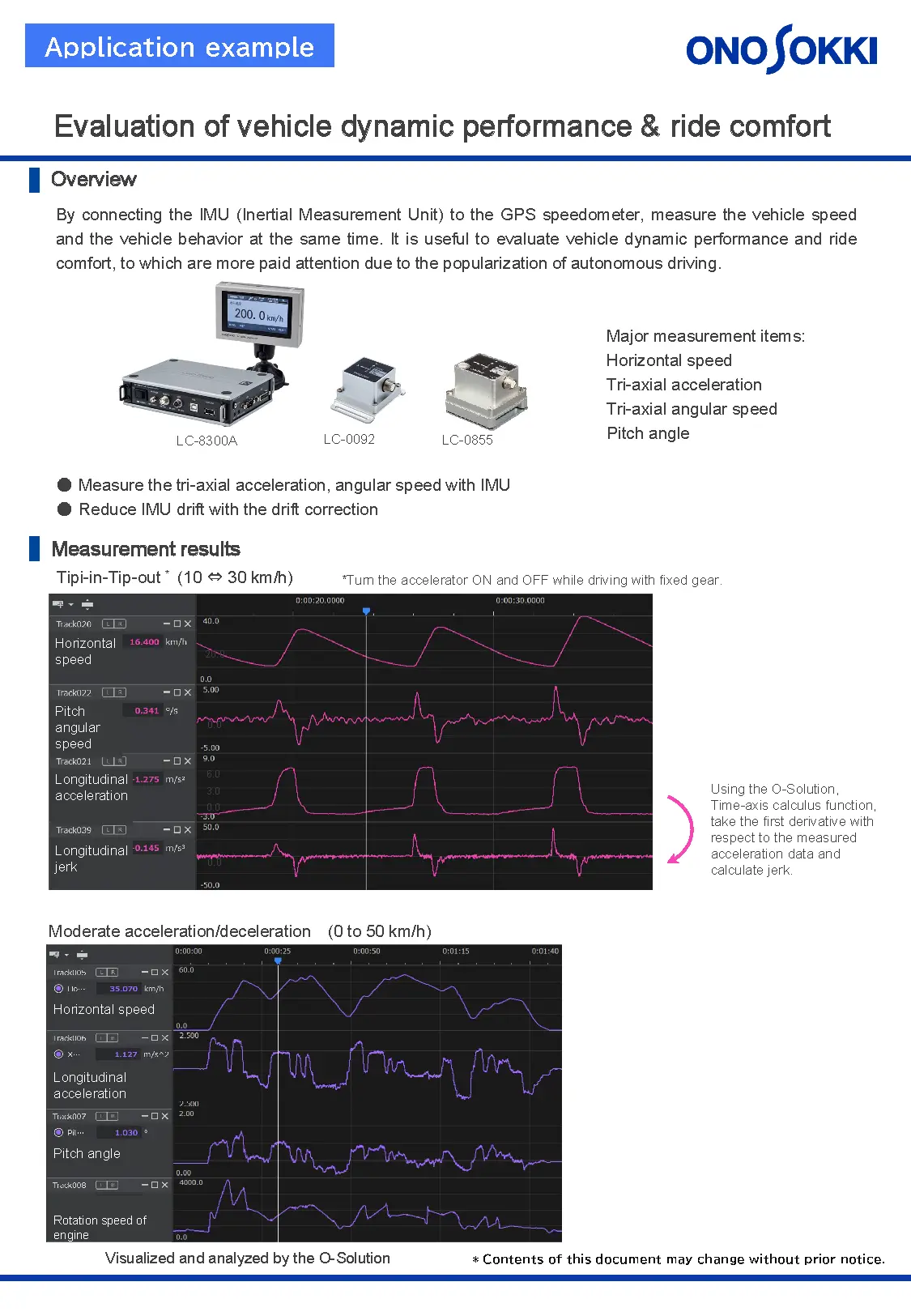
- Horizontal speed
- Tri-axial acceleration
- Tri-axial angular speed
- Pitch angle
- Windows® 10, Windows® 11, Windows® 11 Enterprise LTSC are registered trademarks of Microsoft Corporation in the United States and other countries.
- Intel, Intel logo, Intel Core, Core Inside are trademarks of Intel Corporation in the United States and other countries.
- Windows® 11 Enterprise has been tested and verified to operate correctly in environments using the default configuration (including standard policy settings). We do not guarantee compatibility in environments where default settings have been modified—such as changes to security configurations, group policies, or the use of third-party security software. As a result, support for operation in such customized environments may be limited.
As a JCSS accredited company, we provide calibration services for the LC-8000 series. The JCSS calibration certificate meets the requirements of IATF 16949 Section 7.1.5.3.2*3 and can be used by companies that have already obtained IATF 16949 certification.
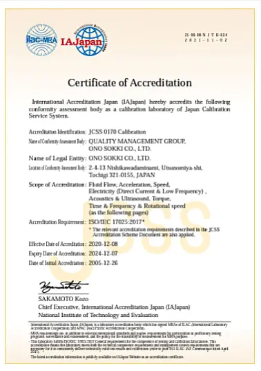
*1: JCSS stands for Japan Calibration Service System. Ono Sokki can issue the calibration certificates with the JSCC accreditation symbol, which is acceptable in the world through the ilac-MRA.
*2: IATF16949 is an international standard for quality management systems
specific to the automotive industry. Many automobile manufacturers around the world have adopted it as a global procurement standard for automobile
parts.
*3: In the section 7.1.5.3.2, the instrument calibration certificate shall be calibrated by the laboratory accredited by ISO/IEC 17025 and the certificate shall include the mark of a national accreditation body.
Case study
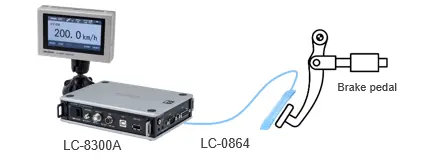
Deceleration and braking distance in braking test, drift amount measurement
It calculates evaluation indexes for braking tests such as deceleration and braking distance, and measures the amount of drift during vehicle braking.
Major measurement items:
| Model | Product name |
|---|---|
| LC-8300A | GPS Speedometer |
| LC-0828N | Hardware Brake Test function |
| LC-0831 | Acceleration/Deceleration Test function |
| LC-0833 | Orbit Display Software |
| LC-0864 | Tape switch |
Evaluation of vehicle dynamic performance & ride comfort
By connecting the IMU (Inertial Measurement Unit) to the GPS speedometer, measure the vehicle speed and the vehicle behavior at the same time. It is useful to evaluate vehicle dynamic performance and ride comfort, to which are more paid attention due to the popularization of autonomous driving.
Major measurement items:
| Model | Product name |
|---|---|
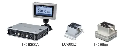
| LC-8300A | GPS Speedometer |
| LC-0092 | Inertial Measurement Unit (IMU) |
| LC-0855 | High precision IMU |
| LC-0836 | IMU data Output function |
| LC-0827 | Hardware Acceleration Test function |
| LC-0831 | Acceleration/Deceleration Test function |
| CT-6710 | Motor & Engine Tachometer |
| IP series | Engine Tachometer |
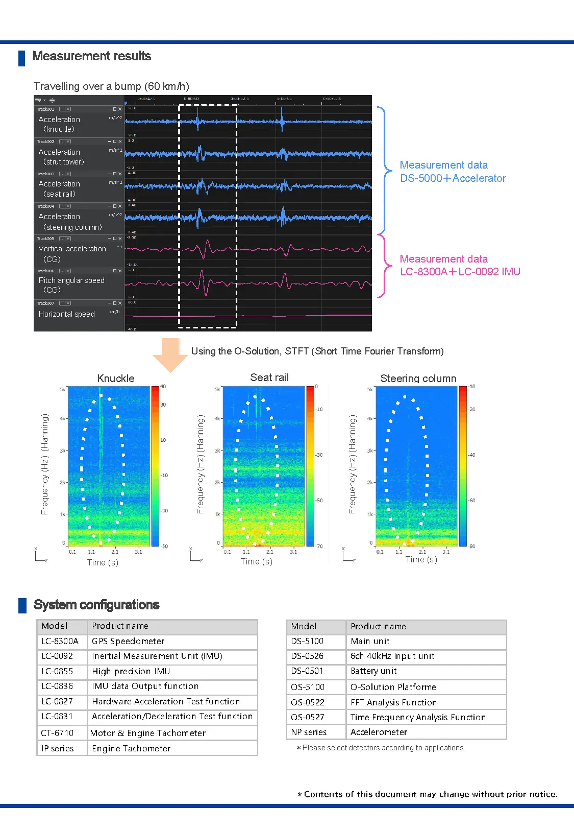
| Model | Product name |
|---|---|
| DS-5100 | Main unit |
| DS-0526 | 6ch 40kHz Input unit |
| DS-0501 | Battery unit |
| OS-5100 | O-Solution Platforme |
| OS-0522 | FFT Analysis Function |
| OS-0527 | Time Frequency Analysis Function |
| NP series | Accelerometer |
Learn more
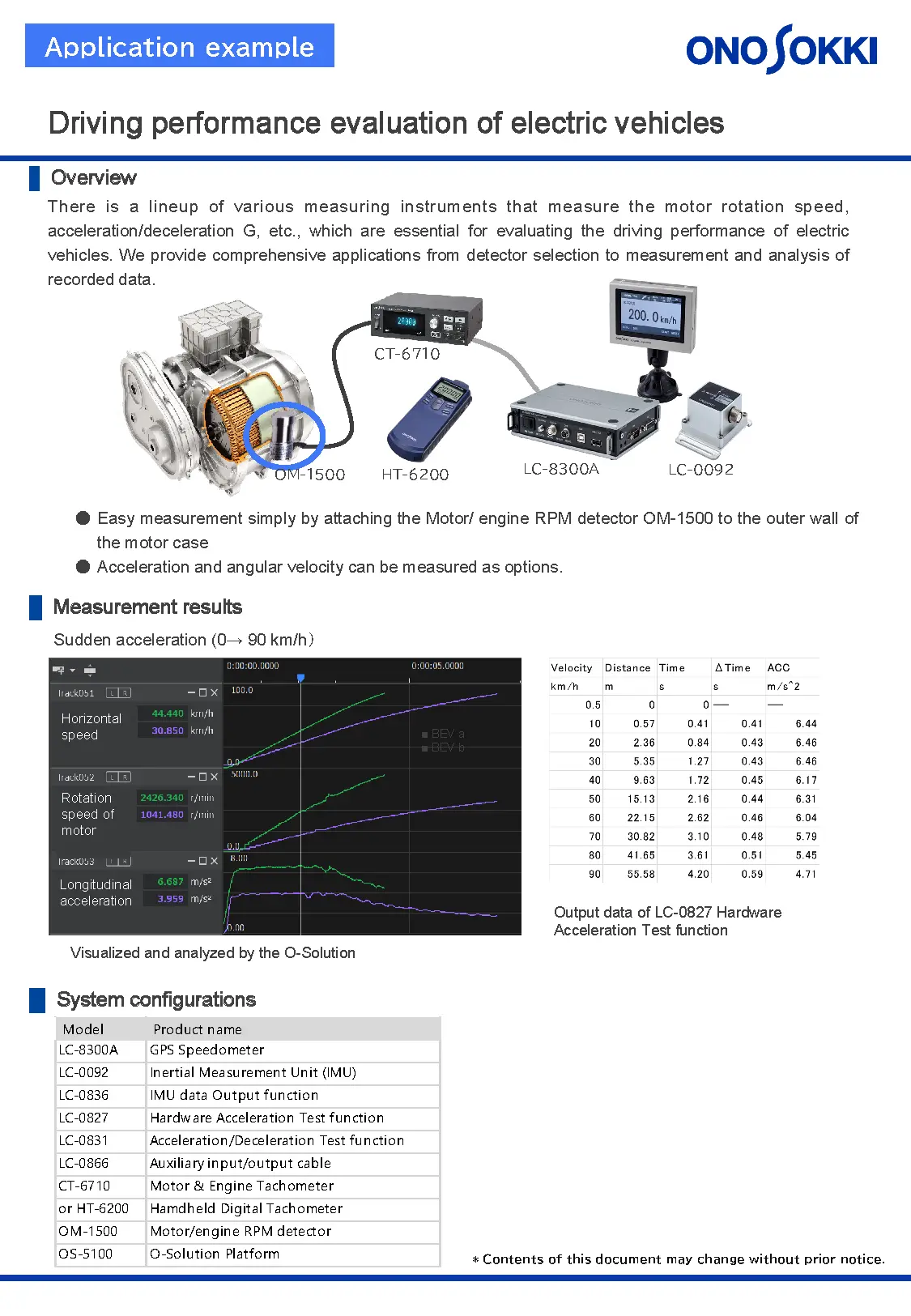
Driving performance evaluation of electric vehicles
There is a lineup of various measuring instruments that measure the motor rotation speed, acceleration/deceleration G, etc., which are essential for evaluating the driving performance of electric vehicles. We provide comprehensive applications from detector selection to measurement and analysis of recorded data.
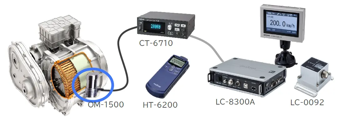
| Model | Product name |
|---|---|
| LC-8300A | GPS Speedometer |
| LC-0092 | Inertial Measurement Unit (IMU) |
| LC-0836 | IMU data Output function |
| LC-0827 | Hardware Acceleration Test function |
| LC-0831 | Acceleration/Deceleration Test function |
| LC-0866 | Auxiliary input/output cable |
| CT-6710 or HT-6200 |
Motor & Engine Tachometer |
| Hamdheld Digital Tachometer | |
| OM-1500 | Motor/engine RPM detector |
| OS-5100 | O-Solution Platform |
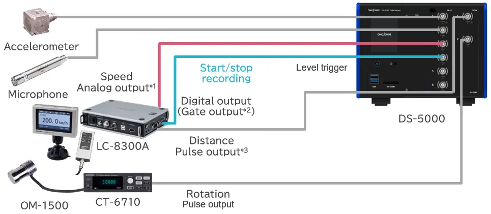
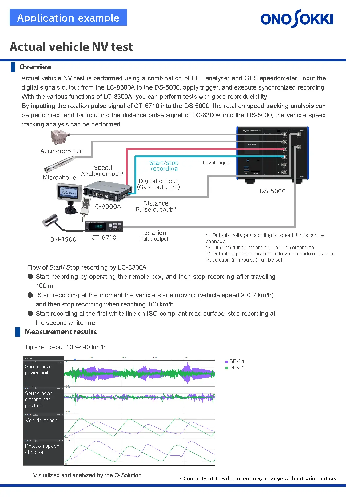
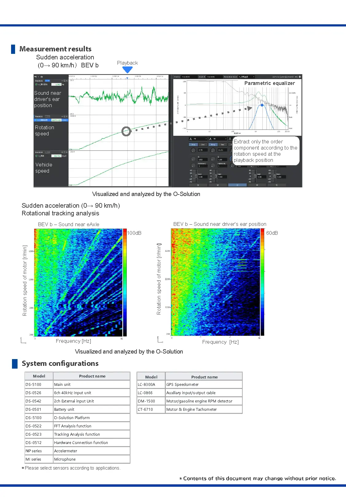
Actual vehicle NV test
Actual vehicle NV test is performed using a combination of FFT analyzer and GPS speedometer.
Input the digital signals output from the LC-8300A to the DS-5000, apply trigger, and execute synchronized recording.
With the various functions of LC-8300A, you can perform tests with good reproducibility.
By inputting the rotation pulse signal of CT-6710 into the DS-5000, the rotation speed tracking analysis can be performed,
nd by inputting the distance pulse signal of LC-8300A into the DS-5000, the vehicle speed tracking analysis can be performed.
| Model | Product name |
|---|---|
| LC-8300A | GPS Speedometer |
| LC-0866 | Auxiliary input/output cable |
| CT-6710 | Motor & Engine Tachometer |
| OM-1500 | Motor/engine RPM detector |
| Model | Product name |
|---|---|
| DS-5100 | Main unit |
| DS-0526 | 6ch 40kHz Input unit |
| DS-0542 | 2ch External input Unit |
| DS-0501 | Battery unit |
| OS-5100 | O-Solution Platform |
| OS-0522 | FFT Analysis function |
| OS-0523 | Tracking Analysis function |
| OS-0512 | Hardware Connection function |
| NP series | Accelermeter |
| MI series | Microphone |
Learn more
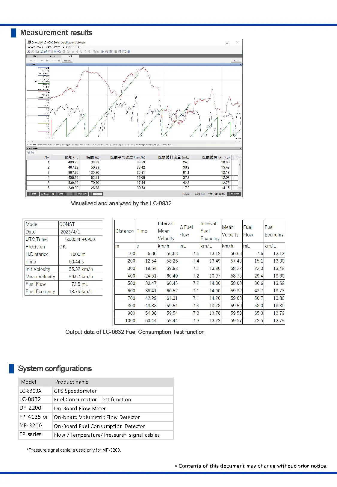
Actual vehicle fuel consumption test
The GPS speedometer and the flow detector are installed in the vehicle to measure the actual vehicle fuel consumption (constant-speed fuel consumption, pattern-mode fuel consumption).
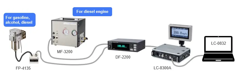
| Model | Product name |
|---|---|
| LC-8300A | GPS Speedometer |
| LC-0832 | Fuel Consumption Test function |
| DF-2200 | On-Board Flow Meter |
| FP-4135 or MF-3200 |
On-board Volumetric Flow Detector |
| On-Board Fuel Consumption Detector | |
| FP series | Flow / Temperature/ Pressure signal cables |
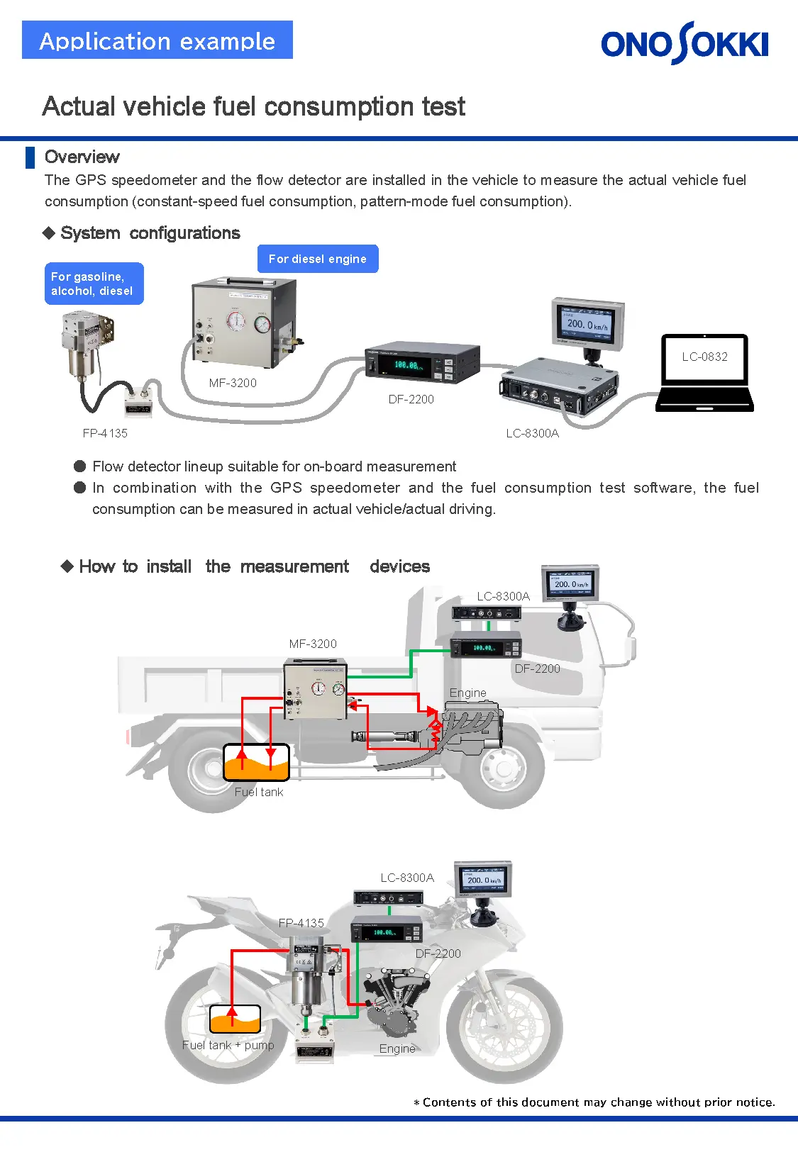
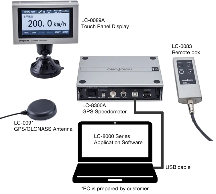
System configuration
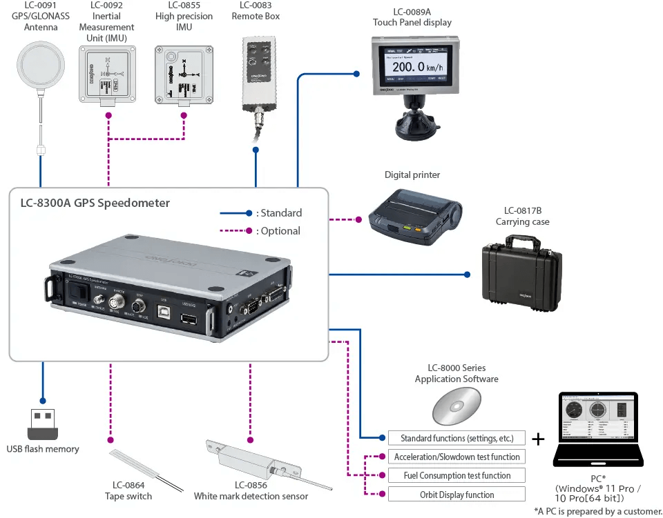
Standalone Test Mode (PC-less)
A simple configuration consisting of only the LC-8300A GPS speedometer and peripherals. Settings such as test conditions are performed on the touch panel display. Test results are recorded in the built-in storage or USB memory (CSV format). After the test is completed, the data can be transferred to a PC and showed on a graph using application software.
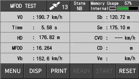
Display test results on the touch panel display
Recorded data example (MFDD mode)
PC Test Mode
By connecting the LC-8300A and a PC with a USB cable, the various tests and measurements performed from the application software. This mode allows you to check the recorded data on a graph during measurement or test. After setting the detailed conditions in the application software, remove a USB cable and perform the test without a PC (Standalone Test Mode).
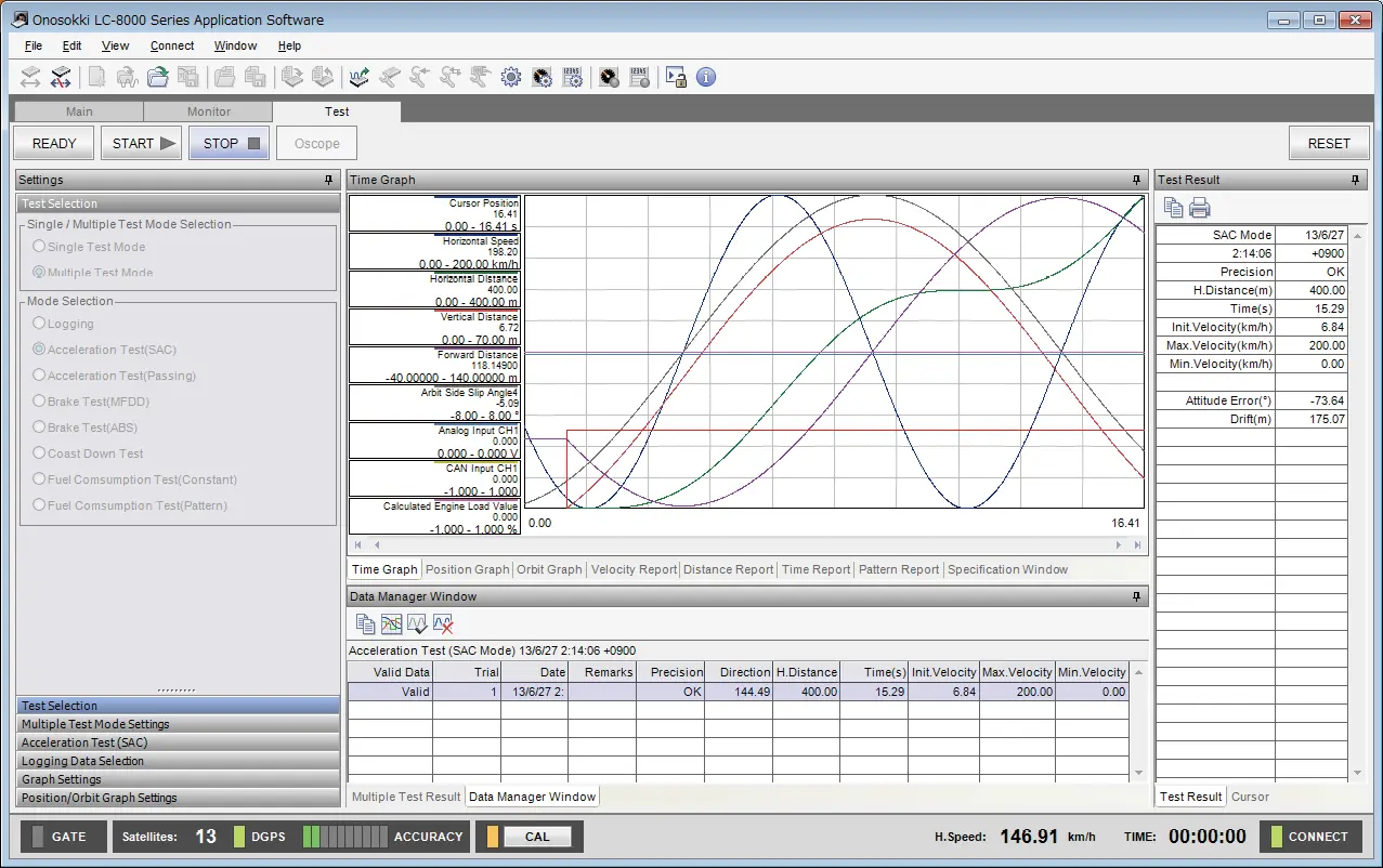
Test results are displayed on the application software and saved on the PC.
* When the PC Test mode is activated,
operation of the LC-0089A touch panel display is disabled.
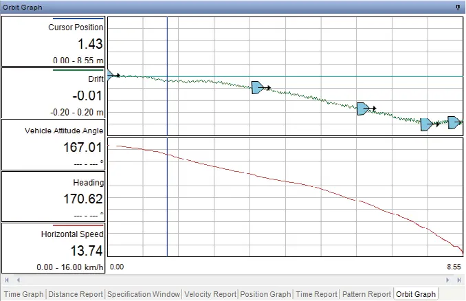
Display example: Drift measurement*
*LC-0833 Orbit Display Software is used.
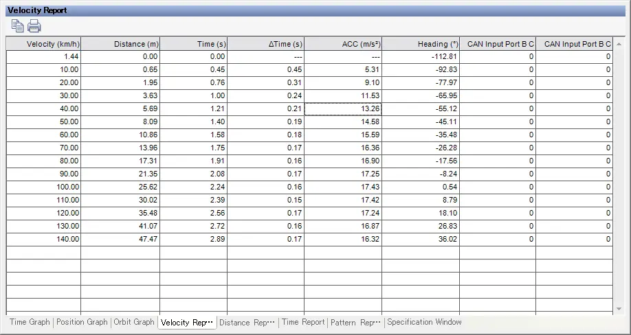
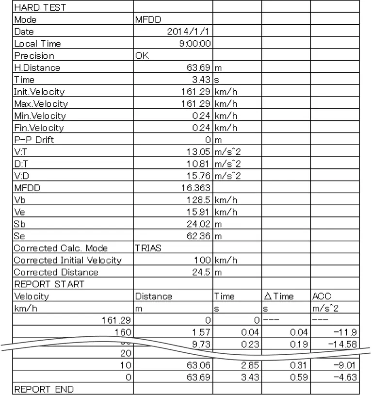
Display example: Velocity report
Veihcle testing function
| Function | Contents | Conforming law | Options | ||
|---|---|---|---|---|---|
| Standalone Test Mode | PC Test Mode | ||||
| Basic Test Mode | Horizontal speed, horizontal distance | - | Standard | Standard | |
| Periodic Measuring Test | Calculation of average speed, maximum speed and minimum speed from the start to the end of measurement | - | |||
| Acceleration Test | Standing Start Acceleration | Measurement of the arrival time until the vehicle reaches the distance of 200 or 400 m. Measurement of the time required to reach a vehicle speed of 100km/h. | - | LC-0827 | LC-0831 |
| Passing Acceleration | Measurement of the time from the start of acceleration until reaching the specified speed. Measurement of the time when accelerating every 10 km/h or 10 m. |
- | |||
| Brake Test | MFDD | Calculation of mean fully developed deceleration | UN-ECE R13-H(Annex 3 1.1.2.) | LC-0828N | |
| UN-ECE R13(Annex 4 1.1.2.) | |||||
| ABS | Calculation of maximum deceleration Z | - | - | ||
| Wet grip | Calculation of average braking deceleration | UN-ECE R117(Annex 5 4.1.6.1.) | |||
| Fade | Calculation of mean fully developed deceleration with continuous braking and at high temperature | - | Made to order | - | |
| - | |||||
| UN-ECE R13(Annex 4 Type-I test, Type-III test) | |||||
| Coasting Test | Calculation of coasting time | Road Transport Vehicle Act- Safety Regulations- Detailed Notification- Appendix 42 I (Measurement Methods for Exhaust Gas Emissions from Light and Medium-Duty Vehicles)- JC08 test cycle (Annex 4: Method for measuring running resistance and setting load on chassis dynamometer 3.1.1.) | LC-0829N | LC-0831 | |
| Fuel Consumption test | Constant-speed fuel consumption | Calculation of fuel consumption when traveling on a flat road with a constant speed | - | - | LC-0832 |
| Pattern-mode fuel consumption | Calculation of fuel consumption by varied travel patterns | - | |||
| Orbit Analysis | Calculation of drifting value | UN-ECE R13-H(Annex6 5.3.6.) | - | LC-0833 | |
| UN-ECE R13(Annex13 5.3.6.) | |||||
| Measurement of minimum rotation radius | - | ||||
Specifications
| Measurement accuracy | Horizontal speed | Measurement range/ accuracy | 0.1 to 500.0 km/h/within ±0.1 km/h (Horizontal speed 30 km/h or more, when 7 or more of satellite acquisition, in the absence of a multipath) |
||||||||||||||||||||||||||||
|---|---|---|---|---|---|---|---|---|---|---|---|---|---|---|---|---|---|---|---|---|---|---|---|---|---|---|---|---|---|---|---|
| Horizontal distance | Accuracy | ±0.1%: when using built-in IMU, external IMU ±0.05%: when using the High-Sensitive IMU (Horizontal speed 30 km/h or more, when 7 or more of satellite acquisition, in the absence of a multipath) | |||||||||||||||||||||||||||||
| Standard measurement item | Horizontal speed (km/h), horizontal distance (m), time (s), UTC time, number of satellite capture, HDOP(Horizontal Dilution of Precision), heading (°), North speed (km/h), East speed (km/h), North distance (m), East distance (m), latitude (dms), longitude (dms), altitude (m ) | ||||||||||||||||||||||||||||||
| Optional measurement item | Lateral distance (m),
vertical speed (km/h),
vertical distance (m),
VDOP(Vertical Dilution of Precision) ,
lateral sideslip amount (m),
travelling distance (m),
roll angle (°),
pitch angle (°),
yaw angle (°), X acceleration (m/s2),
Y acceleration (m/s2),
Z acceleration (m/s2), X angular speed (°/s), Y angular speed (°/s), Z angular speed (°/s), gradient (%) |
||||||||||||||||||||||||||||||
| Update (output)frequency | 100 Hz | ||||||||||||||||||||||||||||||
| General specification | Power requirement | DC 9 to 28 V (non-isolation), AC 100 to 240 V (AC adapter used : option) / 14 W max (DC power input, when connected peripheral devices) |
|||||||||||||||||||||||||||||
| Operating/Storage temperature | Main unit | 0 to 50 °C / -10 to +60 °C (Humidity 20 to 95 %RH, with no condensation) |
|||||||||||||||||||||||||||||
| Antenna | -40 to 85 °C / -40 to 85 °C | ||||||||||||||||||||||||||||||
| Protection class | Antenna | IP67 | |||||||||||||||||||||||||||||
| Vibration resistance | 27.1 m/s2 | ||||||||||||||||||||||||||||||
| Impact resistance | 500 m/s2 | ||||||||||||||||||||||||||||||
| Outer dimensions/weight | Main unit | Approx. 170 × 120 × 40 mm (not including protruded section) Approx. 750 g | |||||||||||||||||||||||||||||
| Display unit | Approx. 132 × 86 × 33 mm (not including protruded section) Approx. 450 g | ||||||||||||||||||||||||||||||
| Remote box | Approx. 115 x 45 x 20 mm (not including protruded section) Approx. 80 g | ||||||||||||||||||||||||||||||
| Antenna | Approx. Φ57 × 15 mm (antenna section) Approx. 110 g (not including cable) | ||||||||||||||||||||||||||||||
| Output | Speed analog output | Range | 0 to 10 V SI Units : 0 to 10 V/0 to 500.0 km/h mile units : 0 to 10 V/0 to 250.0 mile/h |
||||||||||||||||||||||||||||
| Load resistance | 10 kΩ or more | ||||||||||||||||||||||||||||||
| Distance pulse output | Resolution | SI Units : 10, 5, 1 mm/pulse mile Units : Selectable from 16.0934, 8.0467, 1.6093 mm/pulse |
|||||||||||||||||||||||||||||
| Output delay time | 10 ms or less | ||||||||||||||||||||||||||||||
| Output signal | Square wave pulse output Hi 5 V ± 0.5 V, Lo 0.5 V or less | ||||||||||||||||||||||||||||||
| Duty | 50 % ± 10 % | ||||||||||||||||||||||||||||||
| Load resistance | Load 10 kΩ or more | ||||||||||||||||||||||||||||||
| Digital output | Selectable from Gate output/Velocity determination output | ||||||||||||||||||||||||||||||
| Input | Voltage input *1 | Number of channels | 4 | ||||||||||||||||||||||||||||
| Resolution | 16 bit | ||||||||||||||||||||||||||||||
| Range | ±20 V | ||||||||||||||||||||||||||||||
| Sampling frequency | 100 Hz | ||||||||||||||||||||||||||||||
| Analog trigger function | Trigger function for starting or terminating measurement according to voltage. CH1 : measurement start trigger, CH1 : measurement start trigger |
||||||||||||||||||||||||||||||
| Pulse input *1 | Number of channels | 1 | |||||||||||||||||||||||||||||
| Input coupling | AC or DC | ||||||||||||||||||||||||||||||
| Function | Pulse count/frequency/duty | ||||||||||||||||||||||||||||||
| Input waveform | AC selected : sine wave DC selected : square wave |
||||||||||||||||||||||||||||||
| External Trigger Input | Selectable from no-voltage contact/voltage contact | ||||||||||||||||||||||||||||||
| CAN | Common specification | Baud rate | 125 k, 250 k, 500 k, 1000 k bps | ||||||||||||||||||||||||||||
| Protocol | Conforms to CAN Ver2.0B | ||||||||||||||||||||||||||||||
| Input | Input port | 2 (port A, port B) | |||||||||||||||||||||||||||||
| Number of data acquisition | 32ch/1 port (64ch max.) | ||||||||||||||||||||||||||||||
| Others | CAN input should be selected at port B side. | ||||||||||||||||||||||||||||||
| Output *2 | Output update frequency | Selectable from OFF/1 Hz/5 Hz/10 Hz/20 Hz/100 Hz | |||||||||||||||||||||||||||||
| Output item (standard) | Horizontal speed (km/h), speed unit, horizontal distance, (m), UTC time, number of satellite acquisition, trigger of start/stop/reset, GATE status, internal condition, accuracy condition, HDOP (Horizontal Dilution of Precision), heading (°), latitude (dms) , longitude (dms), altitude (m) | ||||||||||||||||||||||||||||||
| Output item (option) | Vertical velocity (km/h), vertical distance, (m), VDOP (Vertical Dilution of Precision),
drift amount (m), roll angle (°), pitch angle (°), yaw angle (°), X acceleration (m/s2), Y acceleration (m/s2), Z acceleration (m/s2), X angular speed (°/s), Y angular speed (°/s), Z angular speed (°/s), gradient (%) |
||||||||||||||||||||||||||||||
| Others | CAN input function at B port side is not available when the output function is enable. | ||||||||||||||||||||||||||||||
| Remarks | Input from CAN connector side. | ||||||||||||||||||||||||||||||
| Other function | Buzzer, DC12 V output for general-purpose sensor, condition memory, print by optional printer, storage function | ||||||||||||||||||||||||||||||
| Test function | Basic test function of hardware | Basic measurement, periodic measuring test | |||||||||||||||||||||||||||||
| Optional test function of hardware | Starting acceleration test, passing acceleration test, brake test (MFDD), brake test (ABS), fade recovery test, coasting test | ||||||||||||||||||||||||||||||
| Basic function of the PC application *3 | Basic function (setting of hardware, display of PC measurement result, and so on.) | ||||||||||||||||||||||||||||||
| Optional function of the PC application *3 | Acceleration/deceleration test software, Fuel consumption test software, Orbit display software | ||||||||||||||||||||||||||||||
| Accessory |
|
||||||||||||||||||||||||||||||
*1 Input by connecting an option cable to the AUX connector on the side to input.
*2 Option
*3 Refer to PC operating environment
LC-0092 Inertial Measurement Unit (IMU) (Optional)
| X/Y/Z acceleration |
|
||||
|---|---|---|---|---|---|
| X/Y/Z angular velocity |
|
||||
| Operating/Storage temperature range | 0 to +50 °C / –10 to +60 ° (Humidity: 20 to 95 %RH with no condensation) |
||||
| Cable length | Approx. 5 m | ||||
| Degree of protection | IP43 | ||||
| Outer dimensions / Weight | Approximately 56 × 56 × 35 mm (Protruding portions not included)/ Approximately 110 g |
*Representative accuracy (that shows the actual performance of the product as evaluated under our specified conditions )
LC-0855 High-Sensitive IMU (Optional)
| X/Y/Z acceleration |
|
||||
|---|---|---|---|---|---|
| X/Y/Z angular velocity |
|
||||
| Operating/Storage temperature range | 0 to +50 °C / –10 to +60 ° (Humidity: 20 to 95 %RH with no condensation) |
||||
| Cable length | Approx. 5 m | ||||
| Degree of protection | IP43 | ||||
| Outer dimensions / Weight | Approximately 72 × 72 × 43 mm (Protruding portions not included) / Approximately 200 g Approximately 72 × 72 × 56 mm (Protruding portions not included) / Approximately 400 g with a magnet |
*Representative accuracy (that shows the actual performance of the product as evaluated under our specified conditions )
LC-0856 White Mark Detection (Optional)
| Power supply voltage | D12 to 24 VDC |
|---|---|
| Current consumption | 30 mA or less |
| Light source | Red semiconductor laser (wave length:655 nm) |
| Emitted light output | 0.5 mW or less |
| Detection distance | 0.2 to 1.5 m |
| Laser spot diameter | Approx. 5 m |
| Reflective sheet | Use supplied reflective sheet (1 m X 2) |
| Operating temperature range | 0 to +50 °C |
| Degree of protection | IPX3 |
| Outer dimensions | Approx.300 × 40 × 45 mm |
| Weight | Approx.350 g (not including cable) |
| OS | LC-8000 Series Application Software:Windows® 11 Pro/10 Pro [64 bit],Windows® 11 Enterprise
LTSC Please refer to the software operating environment [Windows] for the details of the version. |
|---|---|
| Memory | 8 GB or more |
| Storage | 80 GB or more |
| CPU | Intel® Core™ i5 and 8th Generation or later generation 1.6 GHz or more base clock |
| Display | FHD 1920 x 1080 recommended Confirmed to work with text, apps, and other items set to 100% size. |
| USB | USB2.0 (high speed) 1 port or more |
| Optical drive | Optical drive which can read DVD-R and CD-R is necessary for installation and updating. |
| Others | Installation of .NET Framework 4.8 is required. |
Options
| Model name | Product name | Contents |
|---|---|---|
| LC-0827*1 | Hardware Acceleration Test function | [Standalone Test Mode] Implement Standing Start Acceleration Test and Passing Acceleration Test. |
| LC-0828N*1 | Hardware Brake Test function | [Standalone Test Mode] Implement Brake Test (ABS). |
| LC-0829N*1 | Hardware Coastdown Test function | [Standalone Test Mode] Implement Coasting Test. |
| LC-0831 | Acceleration/Deceleration Test function | [PC Test Mode] Implement Acceleration Test, Brake Test and Coasting Test. |
| LC-0832 | Fuel Consumption Test function | [PC Test Mode] Implement Fuel Consumption Test. |
| LC-0833 | Orbit Display function | [PC Test Mode] Create Trajectory Graphs, Calculate Drifting Value. |
| Model name | Product name | Contents |
|---|---|---|
| LC-0824*1 | Km/Mile Selection function | Selectable between km system and mile system Calculated by assuming 1 mile = 1.609344 km (distance and speed) and 1 L = 0.264172053 gallon (related to fuel). |
| LC-0826*1 | Vertical Direction Measurement function | Measure vertical velocity, vertical distance, and slope. |
| LC-0836*1 | IMU data Output function | Measure X, Y, and Z accelerations, X, Y, and Z angular velocities, and roll, pitch and yaw angles. Save and output data from LC-8300A built-in IMU, LC-0092, LC-0855. |
| LC-0854*1 | CAN Output function | Can be used to output CAN data. |
*1 The addition of optional functions after delivery needs to done at factory.
Connecting optional devices
| Model name | Product name | Contents |
|---|---|---|
| LC-0091 | GPS/GLONASS antenna | 5 m cable |
| LC-0092*2 | Inertial Measurement Unit (IMU) | External Inertial Measurement Unit (IMU) with 5 m cable |
| LC-0855*2 | High-Sensitive IMU | Horizontal distance accuracy: ±0.05%, with 5 m cable |
| LC-0856 | White mark detection sensor | Set the timing at which a vehicle reaches the white mark as a trigger for starting or terminating measurement. |
| LC-0864 | Tape switch | Stick it on the brake/accelerator pedal, then trigger when stepping on. |
| LC-0082 | Power supply clip for battery | Red, black clip, cable length 5 m, fuse 3A |
| — | AC adapter for LC-8300A main unit (PS-P20023) | AC 100 to 240 V, power cable sold separately |
| LC-0860 | CAN cable | For CAN communication, 2 m (without terminator) |
| LC-0861 | CAN terminal register adapter | |
| LC-0866 | Auxiliary input/output cable | AUX connector cable (analog input:4 channels, pulse input: 1 channel, digital output) *Can not be used with auxiliary input/output cable for white mark detection sensor connection |
| — | Auxiliary input/output cable for white mark detection sensor connection | *Can not be used with LC-0866. |
| — | Mobile printer (DPU-S445-00C-E) |
Serial printer |
| — | Serial communication cable for printer (PS-D11125A1.5M) |
For connecting LC-8300A and digital printer, cable length 1.5 m |
| — | AC adapter for printer (PW-D0940-W2) |
AC 100 to 240 V |
| — | AC adapter cable for printer (CB-JP04-18A-E) |
For Japan use |
| — | Battery pack for printer (BP-L0725-C1) |
Li-ion battery charger |
| — | Thermal paper for printer (TP-341L-1) |
10 rolls (28 m/roll) |
*2 The installation of options after delivery needs to be done at our factory and calibrations.
Related Information
Last update: 2025/10/20