
![]()
![]()
![]()
Recent development of sound field visualization technology has remarkable progress. Conventionally done, vector maps based on sound pressure level measurement and contour maps using sound intensity had been limited to measuring only a few limited points.
Today, thanks to the low price of microphones and the development of multichannel input devices and processing devices, it is possible to perform simultaneous measurements at more than several dozens of points by acoustic holography method or beam forming method, using a microphone array. Through these methods, it became possible to visualize the sound which was difficult until now with high precision and speed.
The system introduced here uses the near-field acoustic holography method using a microphone array. One is an example of the sound source exploration analysis of a motorcycle engine and the other is an example of tire noise analysis at the time of driving a car.
By grasping the generated sound 3-dimensionally as a flow of energy and efficiently visualizing its size and flow, it becomes possible to quantitatively measure and analyze for the sound evaluation that had been dependent on the human auditory sense so far. Moreover, superimposing on the CCD image on the computer and superimposing with the 3-dimensional data make it possible to show the target sound state in a more comprehensible manner.
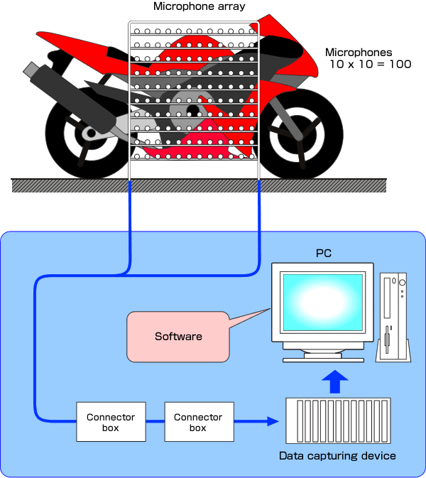
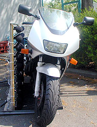
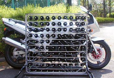
Place the microphone array so as to cover the engine part of the motorcycle. Since it is measured outdoors, windproof screen is attached to each microphone. In order to make it a near field, the distance between each microphone was set to 10 cm, and the distance from the motorcycle was set to 8 cm at the nearest part. The engine rotation speed is fixed at 3000 rpm and time data of 10 seconds is measured.
Measurement principle of near-field acoustic holography
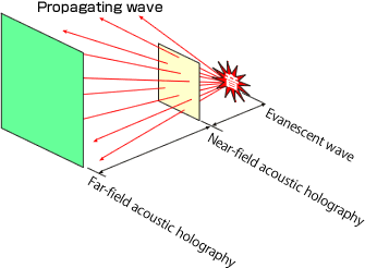
Acoustic holography can be classified into two methods. One is far-field acoustic holography and the other is near-field acoustic holography.
In general, the sound we are listening is a propagating wave from a remote sound source. Far-field acoustic holography is the method that specifies the sound source position by using this propagating wave. However, vibration, emission, and random emission of sound source, for which the information near the sound source is important, cannot be accurately specified by far-field acoustic holography because it is too far to obtain.
The other method, near-field acoustic holography has the feature of high spatial resolution. That is because it acquires the information of near-field sound (evanescent wave) and can measure the sound information near around the emission surface which is canceled by each other at initial propagation. In this example, the sound in the sound source plane and radiation direction are measured and analyzed by using the information of this near field.
System configuration
Please contact your nearest distributor or sales office nearby for more details.Measurement example1:Measurement of motorcycle noise
Measurement of motorcycle noise
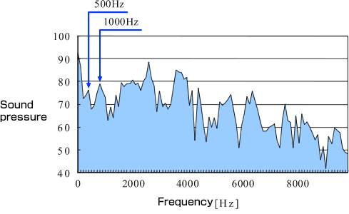
It shows that the frequency characteristics of sound pressure level obtained by microphones arranged in the center area of the microphone array.
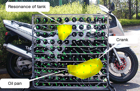
The figure shows the analysis result at 500 Hz. The resolution of sound source generally depends on its waveform length. But, in near-field acoustic holography, the sound source can be separately analyzed by the interval of the microphone because it is very close to the sound source. This analysis result shows that the sound sources at 500 Hz are found at the crank of the engine and lower part of the engine (oil pan etc.). It also shows that the tank resonates due to the vibration of the engine, and the sound is also radiated from the tank area of the engine.
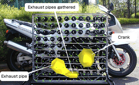
The figure shows the analysis result at 1 kHz. For the sound of 1 kHz, you can see that the sound from the exhaust pipe is considerably radiated in addition to the sound from the center of the engine. As shown example, overlapping the calculation result by holography and image of CCD camera makes the sound source position very easy to grasp.
Measurement example 2: Measurement of tire noise
Measurement of tire noise
When a vehicle performs stationary running, the sound generated from tires is greatly larger ratio than the engine sound etc.
In short, to reduce the environmental noise including those noises from vehicles, it is necessary to grasp the sound position and its largeness generated from tires.
It is well known for experiences that drainage pavement, which has been in spread of use in recent years, contributes greatly to the reduction of sound during running. But its mechanism is not well understood yet.
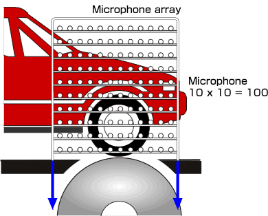
In this example, the tire sound of a passenger car is measured on the chassis dynamo. The test situation is shown in the left figure. The the microphone array is installed at a distance of 10 cm from the tire.
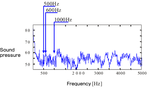
The graph shows the frequency characteristics of tire noise at the representative points. You can see that characteristic peaks are at 500 Hz and 600 Hz, and the sound is generated in 1 kHz band. Generally, the tire groove is created with a random pattern so that the specified peak of running sound does not occur. The distribution of the sound in the 1 kHz band is the result of this countermeasure.
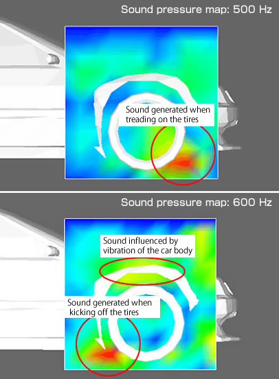
The left shows the sound pressure map of 500 Hz and 600 Hz.
You can see that 500 Hz is the frequency of the sound generated in front of the tire when treading on the tires, and 600 Hz is the frequency of the sound when kicking off with the tires.
This test result shows that the sound source around the tires can be separately shown
by near-field acoustic holography.
It is well known that sound hearing differs according to the tire groove pattern. Through measuring quiet tires and block tires in addition to the tire used in this test by near-field acoustic holography method, the further details that the place and frequency of the noise generated are different depending on the tire have been confirmed .
There are various visualization technologies for sound field. It is necessary to select appropriate method according to the measurement/analysis target or its purpose. As a reference, the following is a comparative table of each measurement method.
| Measurement method | Advantage | Disadvantage |
|---|---|---|
| 3D sound intensity | Obtain sound intensity at measurement point (50Hz to 5kHz) |
Cannot measure transient sound (only stationary sound)Takes long time to measure |
| Beam forming | Measurement from a long distance Measurement range depends on the distance Transient sound analysis |
Resolution depends on the frequency Measures sound pressure Result is shown in 2D Siderobe of beam |
| Near-field acoustic holography | Low frequency dependency in resolution (depends on microphone interval) |
Necessary to close a microphone to the target. Measurement range depends on the size of an array frame. |
Applications of Beam forming method |
|
| ■ | |
Revised:2018/5/31