Operating principle of
Rotary Encoder/Roller encoder
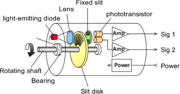
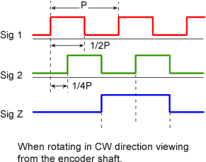
A slit disk is fixed to a rotating shaft of a rotary encoder, which has equally-spaced lattice scale. Opposite to the slit disk, another slit disk with equally-spaced lattice scale is fixed in a main unit of rotary encoder. This two slits are sandwiched in between light-emitting diode and phototransistor. Light from the light-emitting diode is interrupted by rotating shaft every at 1 slit pitch so that this light-dark change is repeated the number of rotations proportional to the rotational amount. The output of a rotary encoder is an electric signal after waveform shaped, which is converted from light-dark change via receiving element. In generally, this output signal is a 2-phase signal adjusted to have 1/4-pitch phase difference each other. By using these signals in combination with a reversible counter having a direction discriminating circuit, it is possible to add and subtract the amount of rotations.


