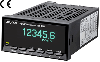
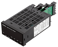
Digital Tachometer
TM-3100 series

The each model of TM-3100 series has the most fundamental function in rotational measurement (display of rotation speed, BCD output, analog output or comparator output) and can be customized by adding optional cards.
The fluorescent display tube of TM-3100 series greatly improves stability and readability instead of using LED as old models.
Features
| TM-3110 |
|
|---|---|
| TM-3120 |
*Output can be optionally changed as Voltage output. |
| TM-3130 |
|
| TM-3140 |
|

Table of optional card combination
| Name of optional card | ||||||
|---|---|---|---|---|---|---|
| TM-0321 BCD output (Voltage Output) | TM-0322 BCD output (open collector) |
TM-0330 Analog output |
TM-0340 Comparator output |
TM-0350 RS-232C |
TM-0301 DC power operated |
|
| TM-3110 | ○ | ○ | ○ | ○ | ○ | ○ |
| TM-3120 | ○ | ◎ | ○ | ○ | × | ○ |
| TM-3130 | ○ | ○ | ◎ | ○ | ○ | ○ |
| TM-3140 | ○ | ○ | ○ | ◎ | ○ | ○ |
Outline of specifications
Common specifications
Input section |
|||||||||||||||||||||
|---|---|---|---|---|---|---|---|---|---|---|---|---|---|---|---|---|---|---|---|---|---|
Input terminal |
M3 free terminal screw | ||||||||||||||||||||
Input impedance |
10 kΩ or more | ||||||||||||||||||||
Input format |
Voltage or non-voltage | ||||||||||||||||||||
| Input amplification | AC or DC | ||||||||||||||||||||
| Applicable detector | Electromagnetic/magneto-electric/photoelectric detector, rotary encoder, proximity switch | ||||||||||||||||||||
AC amplifier |
|
||||||||||||||||||||
DC amplifier |
|
||||||||||||||||||||
Low pass filter |
Selectable from OFF (100 kHz)/100 Hz/20 kHz | ||||||||||||||||||||
| Pulse output section | |||||||||||||||||||||
| Output voltage | Hi level
+4.5 V or more Low level +0.5 V or less |
||||||||||||||||||||
| Output logic | Negative | ||||||||||||||||||||
| Load resistance | 100 kΩ or more | ||||||||||||||||||||
| Output terminal | M3 free terminal screw | ||||||||||||||||||||
Display |
|||||||||||||||||||||
| Display device | Fluorescent display tube (selectable of three-stage brightness, 6-digit display) | ||||||||||||||||||||
| Display refresh time | Selectable from 0.2 s (factory setting), 0.4 s, 0.5 s, 0.6 s, 0.8 s, 1.0 s to 10 s (in 1.0s step). | ||||||||||||||||||||
| Unit of measurement |
|
||||||||||||||||||||
| Number of decimal points | Selectable from OFF (factory setting), number of decimal point of 1, 2 and 3 digit | ||||||||||||||||||||
| SIG indicator | Blink in synchronization with input signal | ||||||||||||||||||||
| Error display | Backup memory error, board error, input frequency error, display digit error, memory full error, setup value error | ||||||||||||||||||||
| Calculation | |||||||||||||||||||||
| Calculation display | Rotation speed, circumferential speed, moving speed, period, times(1/s), frequency, flow, passing time | ||||||||||||||||||||
| Measurement method | Periodic calculation method | ||||||||||||||||||||
| Calculation time | 10 ms + 1 period time | ||||||||||||||||||||
| Measurement accuracy | Display value × (±0.01 %) within ±1 count *The display value indicates the count value except the decimal point. |
||||||||||||||||||||
| Auto zero function | The display value becomes zero with no signal input for
the setup time in advance.
Selectable from below; |
||||||||||||||||||||
| Rapid deceleration follow-up function | If an input signal rapidly decreases and there is no signal input to tachometer approx. 1 second or more, measurement automatically decelerates with this function and then zeroed in approx. 11 seconds later. | ||||||||||||||||||||
| Moving average function | Selectable from below: *Analog output by
TM-3130/0330 is obtained by the processing of |
||||||||||||||||||||
| Peak-hold function | Hold the peak value (maximum, minimum, average) between start and stop status. | ||||||||||||||||||||
| Memory | |||||||||||||||||||||
| Panel condition memory | Memorize 4 kinds of measurement conditions. (The setup conditions can be stored and recalled.) |
||||||||||||||||||||
| Power supply for detector | |||||||||||||||||||||
| Output voltage | 12 VDC ±10 % | ||||||||||||||||||||
| Maximum output current | 100 mA | ||||||||||||||||||||
| General specifications | |||||||||||||||||||||
| Power rating | 100 to 240 VAC (50 Hz/60 Hz) *Cable for power supply is sold separately. |
||||||||||||||||||||
| Withstand voltage | 1500 VAC (1 min) | ||||||||||||||||||||
| Insulation resistance | 10 MΩ or more (at 500 VDC by megohhom ) | ||||||||||||||||||||
| Power rating |
(Power rating is 20 to 30
VA when analog, BCD and |
||||||||||||||||||||
| Operating temperature range | 0 to +50 °C (with no condensation) | ||||||||||||||||||||
| Storage temperature range | -10 to +60 °C (with no condensation) | ||||||||||||||||||||
| Outer dimensions | 96(W) × 48(H) × 140(D) mm max. | ||||||||||||||||||||
| Weight | Approx. 310 g | ||||||||||||||||||||
| Applicable standards |
|
||||||||||||||||||||
| Accessories | Panel mounting fixtures x 1 set | ||||||||||||||||||||
BCD output specifications (TM-3120 and TM-0322 optional card)
| Output signal | |
|---|---|
Output form |
6-digit parallel output |
| Output format | Open collector |
| Sink current | 32 mA max. |
| Output withstand voltage | 24 V max. |
Output logic |
Positive logic |
| Data refresh time | 100 ms or less |
Input signal (request signal) |
|
Input logic |
Negative logic(pulse width:10 μs or more) |
Operating edge |
Falling edge |
Input voltage |
voltage |
Output mode |
|
Mode selector |
Selectable from normal or request |
BCD output specifications (TM-0321 optional card)
TM-0321 card outputs BCD as voltage output. Operation is same as TM-3120 (BCD-open collector).
| Output signal | |
|---|---|
| Output format | TTL |
| Output level | Hi level: +3.8 to +5.25 V, Lo level: 0 to +0.4 V |
Analog output specifications (TM-3130 and TM-0330 optional card)
| Output signal | Selectable form voltage or current |
|---|---|
| Output method | 12bit D/A conversion |
| Output range | Voltage range: Selectable from 0 to 10 V, 0 to 5 V, 1 to
5 V Current range: 4 to 20 mA, 0 to 16 mA |
| Load resistance | Voltage output: 100 kΩ or more Current output: 500Ω or less |
| Linearity | ±0.3%/F.S. |
| Output adjustment | Voltage output: ±5 %/F.S. or more Current output:: ±3 %/F.S. or more |
| Setup accuracy | Voltage output: ZERO ±5 %/F.S., FULL ±5 %/F.S. Current output: ZERO ±3 %/F.S. , FULL ±0.75 %/F.S. |
| Zero drift | ±0.05 %/F.S./ °C |
| Span drift | ±0.05 %/F.S./ °C |
| Output refresh time | Selectable from followings: 10, 20, 50, 100, 200, 500 ms, 1 s |
Note) Adding TM-0330 optional card enables TM-3110, 3150 and 3140 analog output having same as the above specifications.
Comparator function specifications (TM-3140 and TM-0340 optional card)
| Output function | UPPER, LOWER, OK, ERROR outputs
*It outputs OK signal
when both UPPER and LOWER outputs are OFF. |
|---|---|
| Setup | UPPER setup: 6- digit numeric input The relay is ON when
UPPER ≤ displayed value.
LOWER setup: 6-digit numeric input The relay is ON when LOWER > displayed value. |
| Output format | 1-make contact output
*Three kinds of outputs (COMP1, COMP2 and COMP3) are output independently. UPPER, LOWER, OK, ERROR for each combination of outputs Ex.) COMP1=LOWER, COMP2=UPPER, COMP3=ERROR |
| Maximum contact capacity | 30 VDC/1 A, 250 VAC/1 A |
| Output refresh time | Approx. 10 ms |
| Reset | Reset output level to be contact OFF |
| Automatic recover | UPPER, LOWER, or OK output *The rotation speed of recovery can be changed by using hysteresis function. Measurement range: 0 to 20 %, can be setup in 1 % step |
| Output hold | The state of contact ON is hold unless the reset signal is input. |
| Shot output | The time of holding the contact ON (shot time) can be
changed. The state will automatically recover after the
holding time.
Setup range: 10 to 2000 ms in 10 ms steps |
| Delay | The state will be contact ON when the rotation speed
exceeds continuously for the setup time or more in
advance.
Setup range: OFF (0) to 1000 ms in 10 ms steps |
RS-232C/gate function specifications (TM-0350 optional card)
| RS-232C | |
|---|---|
| Communication method | Serial communication (asynchronous) |
| Baud rate | Selectable from 9600 bps or 19200 bps |
| Gate function | |
| Control function | Start, stop and reset |
| Calculation function | |
| Rotation change rate | Change value against reference value is calculated for
each measurement item. (rotation speed, circumferential
speed, moving speed, period, passing time, number of
times, flow).
*Reference value: Section average value or user setup (1 to 999999 numeric input) Measurement accuracy: [±0.02 % x maximum section variation±2 counts]/[±0.01 % × reference value±1 count] *Maximum section variation= |(Maximum or minimum value in measurement section whichever having a larger difference from reference value) - reference value| |
| Section data memory function | Calculate and store the average, maximum, minimum values
and section change rate in setup time at every section.
Section time: Selectable from 1 s, 5 s, 10 s, 30 s, 1 min, 5 min, 10 min, 30 min, 60 min Maximum number of sections: 48 sections Memory mode: Ring buffer mode or memory full mode *Ring buffer mode: Delete section memory in order of the oldest one and continue to store the latest section data when number of section data exceeds 48. *Memory full mode: The storing of the data will be completed after the data for 48 sections are stored. |
| Acceleration calculation function | The acceleration data is obtained at every 1 second by
the calculation of rotation speed, circumferential speed
and moving speed.
Display unit: rad/s2, r/s2, m/s2 Measurement accuracy : ±0.02 % × VDEF±2 counts *VDEF: Speed difference for 1 second |
| Reached speed time function | Measuring the time duration until the stop command value
is reached from the start command value in rotation
speed, circumferential speed, and moving speed.
Start command value, stop command value: 0 to 999999 numeric input |
DC power operated card specifications (TM-0301 optional card)
TM-0301 is an voltage output optional card which allows using of DC power.
| Power voltage | 12 to 24 VDC± 5 % |
|---|---|
| Power consumption | TM-3110/3120/3140: 7 VA, TM-3130: 9 VA
*Power rating is approx. 15 VA when analog, BCD and comparator output cards are equipped. |
| Model | Product name |
|---|---|
| TM-3110 | Digital Tachometer (display only) |
| TM-3120 | Digital Tachometer (with BCD output) |
| TM-3130 | Digital Tachometer (with analog output) |
| TM-3140 | Digital Tachometer (with comparator output) |
| TM-0321 | BCD output card (Voltage output) |
| TM-0322 | BCD output card (open collector) |
| TM-0330 | Analog output card |
| TM-0340 | Comparator output card |
| TM-0350 | RS-232C card |
| TM-0301 | Power operated card |
| AA-8207 | BCD cable (3 m) |
| HT-011 | Reflective mark (12-mm square seal) |
Revised:2024/08/07
