
![]()
![]()
![]()
3D Sound Intensity Analysis Software
DS-0225A
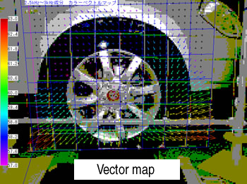
Sound from moving tire
Sound radiation from hot water supplier
Finding out the position where the noise is occurring, and grasping the state of acoustic propagation are important ways to find effective noise countermeasure or improvement of acoustic environment.
Measuring the 3D Sound Intensity*1 near by the sound source is helpful for countermeasure or improvement of noise environment by figuring out the following acoustic trend.
(1)Acoustic energy or acoustic power of the sound source
(2)The detailed sound source position of the target
(3) Flow of acoustic energy radiated from sound source
Features
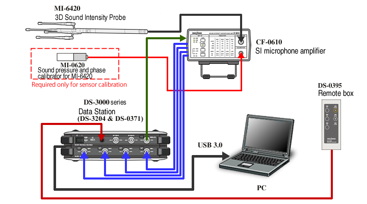
System configuration
| Model name | Product name | Q’ty |
|---|---|---|
| DS-3204 | Data Station Main unit | 1 |
| DS-0371 | 1ch Signal output module (Built-in DS-3200) | 1 |
| MX-105 | Both ends BNC coaxial cable (5 m) | 5 |
| DS-0225A | 3D Sound Intensity Analysis Software | 1 |
| MI-6420 |
3D Sound Intensity Probe | 1 |
| MI-0620 | Sound pressure and phase calibrator for MI-6420 | 1 |
| MI-0602 |
Wind shield screen for SI probe (for low range) | 1 |
| MI-0603 |
Wind shield screen for SI probe (for high range) | 1 |
| CF-0610 | SI microphone amplifier | 1 |
| DS-0395 | Remote box | 1 |
* A PC that satisfies operating conditions is required separately.
Application of Sound Intensity measurement
1. Measurement of radiated road noise
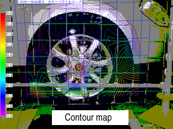
This application simulates a tire travel testing of a passenger vehicle that radiated sound from a tire is measured by 3D Sound Intensity. You can see that the sound flows to forth and back direction from the tire within the frequency range from 2.5 to 3 kHz.
Tire noise: 2.5 kHz to 3 kHz component
2. Measurement of sound distribution in an office
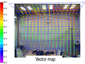
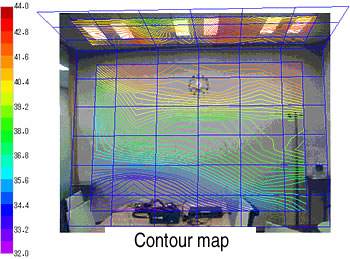
In this application, the process that the noise of 2 kHz to 5 kHz band radiated from the ceiling is decreasing is observed. The measurement inside the room shows the sound leakage through the partition wall, influence of the reflection such as floor. These results will be guidance for countermeasures to make the comfortable space.
Noise in the office: 2 kHz to 5 kHz component
3. Measurement of radiated sound from a hot water supplier
It shows the sound is radiated highly from top and bottom surface, and from upper right part viewed from the front.
Radiated sound in a hot water supply room: 600 Hz component
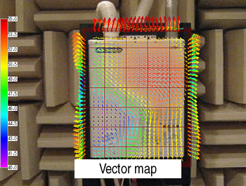
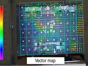
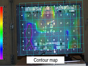
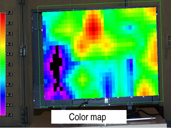
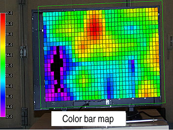
4. Measurement of radiated sound from display panel
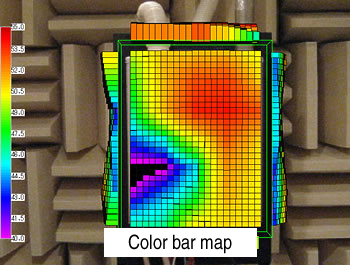
This application measures the sound which is radiated from the front display panel, which is disturbing but not so high sound pressure. The result of sound probing shows that the loud sound is radiated from the middle of the upper part and from slightly left of the center part.
Radiated sound from a display panel: 4 kHz component
![]()
Specification
3D Sound Intensity Analysis Software: DS-0225A| Analysis method | Cross-spectrum method by regular tetrahedron arranged method |
|---|---|
| Spectrum data type | AI*3, RI*4, SP (Sound Pressure), PV (Particle Velocity), each spectrum |
| Measurement frequency range | 40 Hz to 5 kHz |
| Calibration function | Sound pressure sensitivity, phase difference between microphones |
| Measurement for distribution | Up to 10 planes, 1000 measurement points / planes, measurable in XYZ directions, able to overlap up to 5 kHZ. |
| Distribution map | Contour map, color map, vector map etc. |
*3 AI : Active Intensity
*4 RI : Reactive Intensity
MI-6420 (Click here for more details)
| Probe | Regular tetrahedron arranged method MI-6420 Overall length: 560mm, weight 300g, cable length 5m as standard Covered from 40Hz to 5kHz 40Hz to 2kHz: 60mm (Gap length adapter in use) 120Hz to 5kHz: 20mm (Gap length adapter in use) |
|---|---|
| Calibrator | Sound pressure sensitivity correction and phase difference correction by frequency response (MI-0620) Outer dimensions 34(W)x39(H)x183(D)mm Weight:560g Output sound pressure : 94dB (400Hz) |
Operating environment
| OS | Windows® XP (SP2 or later), Windows Vista® (SP2 or later): 32-bit Windows® 7, Windows® 10 : 64-bit |
|
|---|---|---|
* Microsoft®, Windows® are trademarks or registered trademarks of Microsoft Corporation in the United States and other countries.
Revised:2017/09/06