
![]()
![]()
![]()
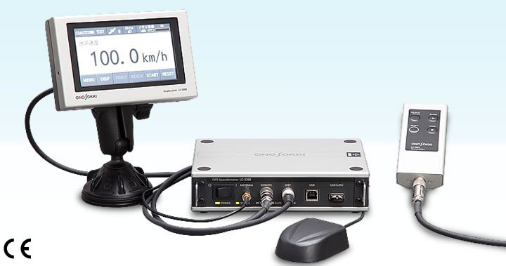
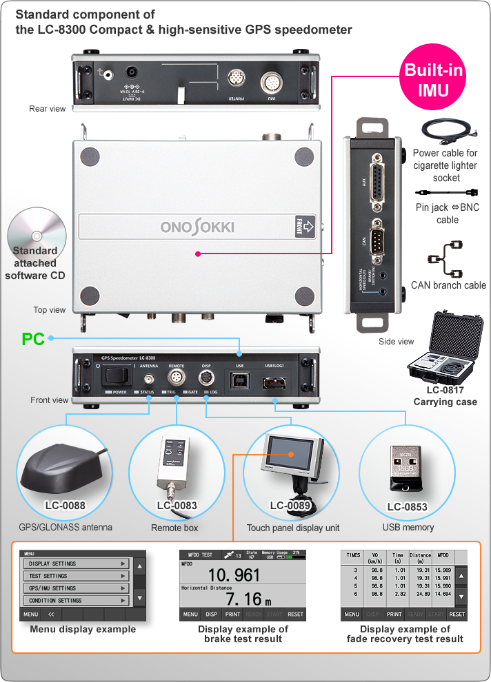
LC-8300 compact and high-sensitive GPS speedometer can measure speed, distance and other vehicle-related measurement items for two-wheel vehicles, or construction vehicles etc. by satellite signals of GPS/GLONASS.
| • | High-sensitive receiver:Allows the GPS/GLONASS antenna to be installed inside a vehicle for measurement. | |
| • | Compact design:170×120×41(mm) and approx.0.75 kg of the main unit, built-in IMU, only three units (main unit, display and antenna) are necessary to measure. | |
| • | Data logging without a PC:Data can be stored in the attached USB memory or internal storage memory. | |
| • | Easy to operate with a touch panel:The touch panel display improves visibility and ease of operation. | |
| • | High accuracy:Accuracy of ±0.2 km/h or less(speed), and ±0.2 % or less (distance) | |
| • | High function:
|
LC-8300 Promotion movie (YouTube)
High accuracy data measurement
– principle of speed measurement using GPS –
The LC-8300 compact & high-sensitive GPS speedometer calculates speed by using Doppler effect of the carrier waveform from GPS satellites.
The Doppler effect is the phenomena that is observed whenever the source of waves such as radio wave, light wave, or sound wave is moving with respect to an observer. The frequency will be high when the observer is approaching to the source, and low frequency when the source is receding.
The following formulas show the Doppler effect of the radio wave and light wave.
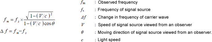
Carrier wave frequency of GPS satellites is controlled very precisely. Measuring the frequency and applying it to the above formula derives the speed V.
However, the ground speed cannot be measured by the carrier wave frequency of only one GPS satellite because GPS satellite is moving at high speed, and also has the effect of the rotation of the earth. Therefore the LC-8300 uses carrier waves from multiple GPS satellites (more than four) to measure the frequency as shown below, and then calculates the speed of the moving object by the same way of positioning measurement method.
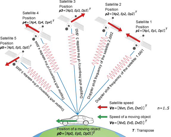
In this method, the speed of the moving object can be calculated extremely more precisely than the calculation method using the amount of position change, because it receives almost none of the influence from the ionosphere.
The accuracy of its horizontal component is 0.003 m/s when 2 σ, 0.08 m/s when 3 σ. However, it shall not apply to the accuracy of the vertical components. As for the accuracy of the vertical component, the accuracy turns worse approx. 3 times in comparison with the accuracy of the horizontal components because it receives a satellite signal from only a single direction. From the image above, you can see that the moving object is receiving the radio waves of various Doppler shift frequencies from multiple satellites.
The formulation of these relationships is as follows.
Δ fd1 = 1/ λ (V0 - V1)· u1
Δ fd2 = 1/ λ (V0 - V2)· u2
Δ fd3 = 1/ λ (V0 - V3)· u3
Δ fd4 = 1/ λ (V0 - V4)· u4
Δ fd5 = 1/ λ (V0 - V5)· u5
λ is wavelength of carrier waveform radiated from a satellite; approx. 0.19m, fb represents clock error of a receiver; (Hz), and un (n = 1..5)shows visual direction unit vector of a satellite and a receiver position. Those can be calculated by the following formulas.
un =ρ n/| ρ n| (n = 1..5)
ρ n =[ (Npn - Np0), ( Epn - Ep0), ( Dpn - Dp0)]T (n =
1..5)
The speed of a moving object can be calculated by solving Vo with these formulas.
Stable measurement
– Correction processing by IMU –
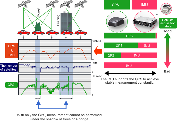
A big noise is occurred in speed output of the Doppler method on a public road in city area. Because there are enough obstacles to give the influence of multi-path on the measurement such as trees or buildings as shown below. In addition, the speed measurement using GPS alone cannot be performed when the vehicle passes the place that satellite signal cannot be captured, like the viaduct.
Even under the multi-path environment, combining the speed information from GPS and tri-axial accelerometers of IMU/tri-axial gyro with appropriate ratio derives more precise and much smoother speed data output than that of one GPS as is shown below.
Also, interpolation by IMU helps high accurate speed data output at the place where the measurement in GPS alone is not possible in the cases such that a vehicle passes under a viaduct.
Software Options for Hardware/PC test
| LC-8300 Compact & high sensitivity GPS speedometer | ||||
|---|---|---|---|---|
| Hardware test function (PC-less) | PC Test software | |||
Minimum component:main unit, antenna,
display, remote control |
Minimum component:Main unit, antenna, PC |
|||
| Starting acceleration | LC-0827 Hardware acceleration test function |
Starting acceleration | LC-0831 Acceleration/deceleration test software |
|
| Passing acceleration | Passing acceleration | |||
| MFDD | LC-0828 Hardware brake test function |
MFDD | ||
| ABS | ABS | |||
| Fade recovery | - | |||
| Coasting | LC-0829 Hardware coasting test function |
Coasting | ||
| Constant-speed fuel consumption | LC-0832 Fuel consumption test software |
|||
| Fuel consumption at test mode | ||||
*:All test functions listed above are options.
Display example of hardware test measurement
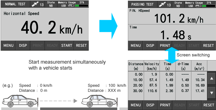
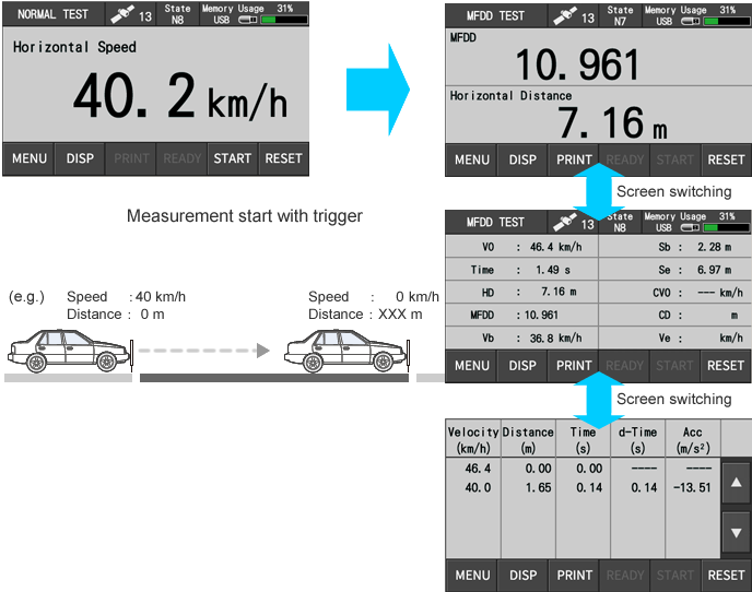
1. Starting acceleration test
Measures the arrival time from a vehicle stop point to the specified speed point or the distance with quick acceleration.
Historical data can be monitored.
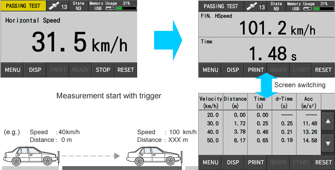
2. Passing acceleration test
3. Brake test (MFDD)
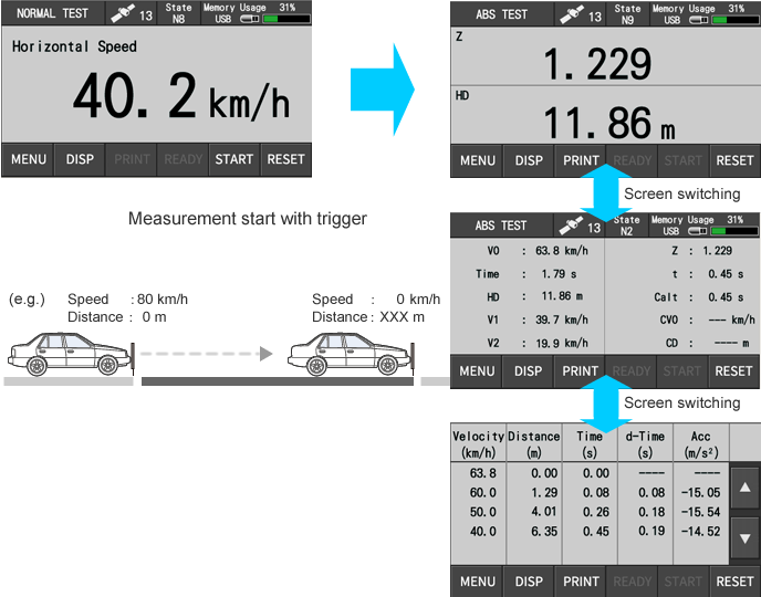
4. Brake test (ABS)
Sets and measures the interval vehicle speed in braking test.
Checks deceleration speed calculated from each parameter, historical data can be monitored.
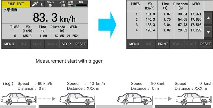
5. Brake test (fade recovery)
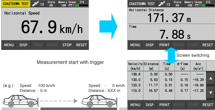
6. Coasting test
| Measurement accuracy | Horizontal speed | Measurement range/ accuracy | 0.1 to 500.0 km/h/±0.2 km/h or less (Horizontal speed 30 km/h or more, when 7 or more of satellite acquisition) | ||||||||||||||||||||||||||||||||||||||||||||
|---|---|---|---|---|---|---|---|---|---|---|---|---|---|---|---|---|---|---|---|---|---|---|---|---|---|---|---|---|---|---|---|---|---|---|---|---|---|---|---|---|---|---|---|---|---|---|---|
| Horizontal distance | Accuracy | ±0.2 % (forward distance 300 m, horizontal speed 30 km/h or more, when 7 or more of satellite acquisition) | |||||||||||||||||||||||||||||||||||||||||||||
| Standard measurement item | Horizontal speed (km/h), horizontal distance (m), time (s), UTC time, number of satellite capture, HDOP(Horizontal Dilution of Precision), Heading (°), North speed (km/h), East speed (km/h), North distance (m), East distance (m), travelling distance (m), latitude (dms), longitude (dms), altitude (m ) | ||||||||||||||||||||||||||||||||||||||||||||||
| Optional measurement item | Lateral distance (m), vertical speed (km/h), vertical distance (m), VDOP(Vertical Dilution of Precision) , lateral sideslip amount (m), roll angle (°), pitch angle (°), yaw angle (°), X acceleration (m/s2), Y acceleration (m/s2), Z acceleration (m/s2), X angular speed (°/s), Y angular speed (°/s), Z angular speed (°/s), gradient (%) | ||||||||||||||||||||||||||||||||||||||||||||||
| Update (output)frequency | 100 Hz | ||||||||||||||||||||||||||||||||||||||||||||||
| General specification | Hardware | Power requirement | DC 9 to 28 V (non-isolation), AC 100 to 240 V (AC adapter used:option)/ 12 VA max (DC power input, when connected peripheral devices) | ||||||||||||||||||||||||||||||||||||||||||||
| Operating/storage temperature | 0 to 50 °C / -10 to 60 °C (humidity 20 to 80 %RH, with no condensation) | ||||||||||||||||||||||||||||||||||||||||||||||
| Outer dimensions /mass | Approx. 170 × 120 × 40 mm (not including protruded section) approx. 0.75 kg | ||||||||||||||||||||||||||||||||||||||||||||||
| Display unit | Outer dimensions /mass | Approx. 132 × 86 × 33 mm (not including protruded section) approx. 0.45 kg | |||||||||||||||||||||||||||||||||||||||||||||
| Remote | Outer dimensions /mass | Approx. 115 x 45 x 20 mm (not including protruded section) approx. 0.08 kg | |||||||||||||||||||||||||||||||||||||||||||||
| Antenna | Outer dimensions /mass | Approx. 66×50×22 mm (antenna section) approx. 0.1 kg | |||||||||||||||||||||||||||||||||||||||||||||
| Protection class | IP67 | ||||||||||||||||||||||||||||||||||||||||||||||
| Output | Speed analog output | Range | 0 to 10 V SI Units:0 to 10 V/0 to 500.0 km/h mile units:0 to 10 V/0 to 250.0 mile/h |
||||||||||||||||||||||||||||||||||||||||||||
| Load resistance | 10 kΩ or more | ||||||||||||||||||||||||||||||||||||||||||||||
| Distance pulse output | Resolution | SI Units:10, 5, 1 mm/pulse mile Units:16.0934, 8.0467, 1.6093 Selectable from mm/pulse |
|||||||||||||||||||||||||||||||||||||||||||||
| Output delay time | 10 ms or less | ||||||||||||||||||||||||||||||||||||||||||||||
| Output signal | Square wave pulse output Hi 5 V ± 0.5 V Lo 0.5 V or less | ||||||||||||||||||||||||||||||||||||||||||||||
| Duty | 50 % ± 10 % | ||||||||||||||||||||||||||||||||||||||||||||||
| Load resistance | Load 10 kΩ or more | ||||||||||||||||||||||||||||||||||||||||||||||
| Remarks | Selectable from voltage or pulse, output from HORIZONTAL SPEED connector on the side | ||||||||||||||||||||||||||||||||||||||||||||||
| Input | Voltage input | Number of channels | 4 | ||||||||||||||||||||||||||||||||||||||||||||
| Resolution | 16 | ||||||||||||||||||||||||||||||||||||||||||||||
| Range | ±20 V | ||||||||||||||||||||||||||||||||||||||||||||||
| Cutoff frequency | 50 Hz | ||||||||||||||||||||||||||||||||||||||||||||||
| Others | The function to set measurement start· stop trigger by voltage value CH1:measurement start trigger CH2:measurement stop trigger |
||||||||||||||||||||||||||||||||||||||||||||||
| Pulse input | Number of channels | 1 | |||||||||||||||||||||||||||||||||||||||||||||
| Input coupling | AC or DC | ||||||||||||||||||||||||||||||||||||||||||||||
| Function | Pulse count/frequency/duty | ||||||||||||||||||||||||||||||||||||||||||||||
| Input waveform | AC selected:sine wave DC selected:square wave |
||||||||||||||||||||||||||||||||||||||||||||||
| Remarks | Input by connecting an option cable to the AUX connector on the side to input | ||||||||||||||||||||||||||||||||||||||||||||||
| CAN | Common specification | Baud rate | 125 k, 250 k, 500 k, 1000 k bps | ||||||||||||||||||||||||||||||||||||||||||||
| Protocol | Conforms to CAN Ver2.0B | ||||||||||||||||||||||||||||||||||||||||||||||
| Input | Input port | 2 (port A, port B) | |||||||||||||||||||||||||||||||||||||||||||||
| Number of data acquisition | 32ch/1 port (64ch max.) | ||||||||||||||||||||||||||||||||||||||||||||||
| Others | CAN input should be selected at port B side. | ||||||||||||||||||||||||||||||||||||||||||||||
| OBDⅡ data acquisition function |
Data aquisition using CAN input port (port A:31 ch / 32 ch)
1. When OBD II data acquisition function is enabled, the maximum number of acquired data of CAN input port A is 30 ch
|
||||||||||||||||||||||||||||||||||||||||||||||
| Output*1 | Output update interval; | Selectable from OFF/1 Hz/2 Hz/5 Hz/10 Hz/20 Hz/100 Hz | |||||||||||||||||||||||||||||||||||||||||||||
| Output item (standard) | Horizontal speed (km/h), speed unit, horizontal distance, (m), UTC time, number of satellite acquisition, trigger of start· stop· reset, GATE status, internal condition, accuracy condition, HDOP (Horizontal Dilution of Precision), Heading (°), latitude (dms) , longitude (dms), altitude (m) | ||||||||||||||||||||||||||||||||||||||||||||||
| Output item (option) | Vertical velocity (km/h), vertical distance, (m), VDOP (Vertical
Dilution of Precision), drift amount (m), roll angle, (°), pitch
angle (°), yaw angle (°), X acceleration (m/s2), Y acceleration (m/s2), Z acceleration (m/s2), X angular speed (°/s), Y angular speed (°/s), Z angular speed (°/s), gradient (%) |
||||||||||||||||||||||||||||||||||||||||||||||
| Others | CAN input function at B port side is not available when the output function is ON. | ||||||||||||||||||||||||||||||||||||||||||||||
| Remarks | Input by AUX connector on the side with optional cable | ||||||||||||||||||||||||||||||||||||||||||||||
| Other function | Buzzer, external trigger input, DC12 V output for general-purpose sensor, condition memory, print by optional printer, storage function | ||||||||||||||||||||||||||||||||||||||||||||||
| Test function | Basic test function of hardware | Normal measurement, Interval measurement test | |||||||||||||||||||||||||||||||||||||||||||||
| Optional test function of hardware | Starting acceleration test, passing acceleration test, brake test (MFDD), brake test (ABS), fade recovery test, coasting test | ||||||||||||||||||||||||||||||||||||||||||||||
| Basic function of the PC application*2 | Basic function (setting of hardware, display of PC measurement result, and so on.) | ||||||||||||||||||||||||||||||||||||||||||||||
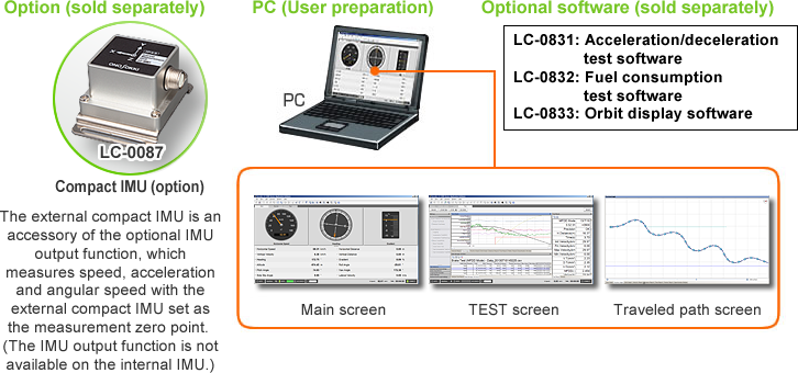
| Optional function of the PC application*2 | Acceleration/deceleration test software, Fuel consumption test software, Track display software | ||||||||||||||||||||||||||||||||||||||||||||||
| Accessory |
|
||||||||||||||||||||||||||||||||||||||||||||||
| Option | <Main unit side>
<Software for PC side>
|
||||||||||||||||||||||||||||||||||||||||||||||
*1:Option
*2:Refer to the following PC operating environment.
| OS | Windows® 10 / 7 [32/64 bit] |
|---|---|
| Memory | 512 MB or more |
| HDD | 80 GB or more |
| CPU | Intel CoreTM2 Duo / 2 GHz or more |
| Display | XGA (1024X768 )or more |
| USB | USB2.0 (high speed) 1 port or more |
| Optical drive | Optical drive which can read DVD-R and CD-R is necessary for installation and updating. |
* Windows® 10 , Windows® 7 are registered trademarks of
Microsoft Corporation in the United States and other
countries.
* Intel, Intel logo, Intel Core, Core Inside are trademarks
of Intel Corporation in the United States and other
countries.
* Other product names and model names are trademarks or
registered trademarks of each individual company. The
copyrights are reserved by each individual company.
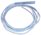
| LC-0864 Tape switch |
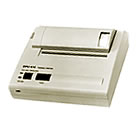
DPU-414 Digital printer |
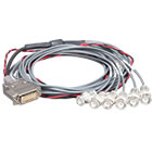
LC-0866 Input/output cable |
|---|---|---|
 |
 |
 |
Revised:2019/1/11