Digital Flow Meter
FM-2500A/1500
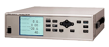
FM-2500A
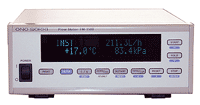
FM-1500
Measurement Module
| FX-0400A | Measurement module for FX-series
Mass-Burette type Gravity Flow Detectors (FM-2500A only) |
|---|---|
| DF-0400A | Measurement module for FP-series Volumetric Flow Detectors |
| FZ-0300A | Measurement module for FZ-series Mass Flow Detectors |
| FM-0210A | Module for result of
addition/subtraction between 2sets of flow detectors (FM-2500A only) |
Features
Applications
(The flow detector area in the following figure is linked to the each product page.)
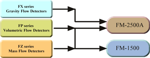
*Please click the following frame to see about Type A, B, C and D.
| Flow Detectors | Applicable measurement modules | Applicable Flow Meters | |
|---|---|---|---|
| FP series Volumetric Flow
Detector × 1 set (Type A Type B) |
DF-0400A × 1 set | FM-2500A | FM-1500 |
| FP series Volumetric Flow
Detector × 2 sets (Type C Type D) |
DF-0400A × 2 sets & FM-0210A × 1 set |
FM-2500A | - |
| FX series Gravity Flow
Detector × 1 set (Type A) |
FX-0400A × 1 set | FM-2500A | - |
| FZ series Mass Flow
Detector × 1 set (Type A Type B) |
FZ-0300A × 1 set | FM-2500A | FM-1500 |
| FZ series Mass Flow
Detector × 2 sets (Type C Type D) |
FZ-0300A × 2 sets & FM-0210A × 1 set |
FM-2500A | - |
Actual screen displays (FM-2500A)
Measurement value display screen
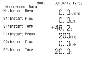
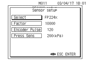
Factor setup screen
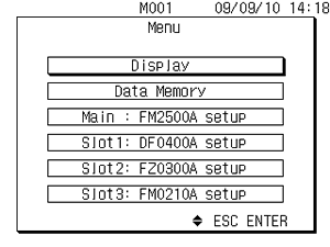
Menu screen display screen
Overview Specification
FM-2500A/1500 Display Unit Specification (+DF-0400A measurement module)
| FM-2500A (FM-2500A + DF-0400A) |
FM-1500 (FM-1500 + DF-0400A) |
|||||||||||||||||||||||||||||||||||||||||||||||||||||||
|---|---|---|---|---|---|---|---|---|---|---|---|---|---|---|---|---|---|---|---|---|---|---|---|---|---|---|---|---|---|---|---|---|---|---|---|---|---|---|---|---|---|---|---|---|---|---|---|---|---|---|---|---|---|---|---|---|
| Applicable flow detectors | FP-213S, FP-213, FP-2140H, FP-2240HA, FP-215 or FP-2250A |
|||||||||||||||||||||||||||||||||||||||||||||||||||||||
| Applicable revolution detectors | MP-9100, MP-981 or LG-916 (*9) | |||||||||||||||||||||||||||||||||||||||||||||||||||||||
| Display method | LCD with CFL backlight 320×240 dots | Fluorescent display tube | ||||||||||||||||||||||||||||||||||||||||||||||||||||||
Displayed items and number of digits |
Time measurement | Sectional total time (*1) | 0.00 to 9999999 s (max. 7 digits) | |||||||||||||||||||||||||||||||||||||||||||||||||||||
| Total time (*1) | ||||||||||||||||||||||||||||||||||||||||||||||||||||||||
| Revolution measurement | Revolution speed | 0.0 r/min (max. 7 digits) | - |
|||||||||||||||||||||||||||||||||||||||||||||||||||||
| Sectional total average revolution speed (*2) | ||||||||||||||||||||||||||||||||||||||||||||||||||||||||
| Sectional total revolution | 0 to 9999999 REV (max. 7 digits) | |||||||||||||||||||||||||||||||||||||||||||||||||||||||
| Total average revolution speed (*3) | 0.0 r/min(max. 7 digits) | |||||||||||||||||||||||||||||||||||||||||||||||||||||||
| Total revolution | 0 to 9999999 REV(max. 7 digits) | |||||||||||||||||||||||||||||||||||||||||||||||||||||||
| Pressure | 0 to 9999 kPa (max. 4 digits) | |||||||||||||||||||||||||||||||||||||||||||||||||||||||
| Temperature | ±0.0 to 999.9 °C(max. 4 digits) | |||||||||||||||||||||||||||||||||||||||||||||||||||||||
Flow rate measurement (max. 7 digits)(*6)(*7) |
|
|||||||||||||||||||||||||||||||||||||||||||||||||||||||
| Measurement time | Instantaneous |
Can be specified within the range of 1 to10 seconds (in 1-second increments) | 1-second |
|||||||||||||||||||||||||||||||||||||||||||||||||||||
Total |
Up to the start time to stop time, specified in the total measurement mode. | |||||||||||||||||||||||||||||||||||||||||||||||||||||||
| Total measurement mode | Manual |
Total from the start to stop signal specified on the panel or by an external signal (communications or remote box the FM-0200) | ||||||||||||||||||||||||||||||||||||||||||||||||||||||
Flow rate setting method |
Total time/revolutions from the start signal up to the specified total flow rate. | Total time from the start signal up to the specified total flow rate. | ||||||||||||||||||||||||||||||||||||||||||||||||||||||
Time setting method |
Total flow rate/revolutions from the start signal up to the specified total time. | Total flow rate from the start signal up to the specified total time. | ||||||||||||||||||||||||||||||||||||||||||||||||||||||
Revolution setting method |
Total flow rate/time from the start signal up to the specified total revolutions. | - |
||||||||||||||||||||||||||||||||||||||||||||||||||||||
| Voltage output (*8) | Flow rate |
0 to 10 V/Low to High (Low and High values are variable.) | 0 to 10 V/0 to F.S. (F.S. value is selectable from 100/200/300/500/1000/1500(kg/h, L/h) | |||||||||||||||||||||||||||||||||||||||||||||||||||||
Pressure |
0 to 10 V/0 to F.S. (F.S. value is selectable from 200/500/980/1000(kPa) | |||||||||||||||||||||||||||||||||||||||||||||||||||||||
Temperature |
0 to 10 V/0 to 100°C | |||||||||||||||||||||||||||||||||||||||||||||||||||||||
| Pulse output | Pulse output |
FP-213S/213:Selectable from Direct/0.001/0.01(mL/P, g/P) FP-2140H/2240HA:Selectable from Direct/0.01/0.1(mL/P, g/P) FP-215/2250A:Selectable from Direct/0.1/1(mL/P, g/P) |
||||||||||||||||||||||||||||||||||||||||||||||||||||||
Output specification |
Frequency range: 0 to 100 kHz Output H level: 2.4 V or more, output L level: 0.8 V or less |
|||||||||||||||||||||||||||||||||||||||||||||||||||||||
(*1) Total value can be displayed up
to 7 digits. The position of the decimal point moves to the
right or left depending on the number of decimal positions
of the values.
(*2) Sectional total average revolution speed = Sectional
total revolution / sectional total time
(*3) Total average revolution speed = Total revolution /
total time
(*4) Sectional total average flow rate = Sectional total
flow rate / sectional total time
(*5) Total average flow rate = Total flow rate / total time
(*6) Displayed value of mass flow rate is converted at
density / temperature / temperature correction coefficient
specified in advance. The conversion by actual measurement
density is available when simultaneous measurement with the
FZ series continuous mass flow meter is performed. (only
the FM-2500A)
(*7) The position of the decimal point in the above table is
when the encoder pulse is set at “120 P/R x multiplier 10”
or “1200P/R (option)”. If the setting at “120P/R” is
selected, the decimal point moves to the right to increase
one digit. If the setting at “1200P/R x multiplier 10” is
selected, the decimal point moves to the left to decrease
one digit.
(*8) Update interval of voltage output: 0.1 seconds,
accuracy: ±0.1%/F.S
(*9) the MP-9100 can be connected via the Mx-0xx series,
MP-981 and LG-916 can be connected via the MX-8000 series
cable.
FM-2500A Display Unit Specification (+FX-0400A measurement module)
| Applicable flow detectors | FX-1110, FX-1120 or FX-1130 | ||||||||||||||||||||||||||||||||||||||||||
|---|---|---|---|---|---|---|---|---|---|---|---|---|---|---|---|---|---|---|---|---|---|---|---|---|---|---|---|---|---|---|---|---|---|---|---|---|---|---|---|---|---|---|---|
| Applicable revolution detectors | MP-9100, MP-981 or LG-916(*8) | ||||||||||||||||||||||||||||||||||||||||||
| Display method | LCD with CFL backlight 320×240 dots | ||||||||||||||||||||||||||||||||||||||||||
| Displayed items and number of digits | Time measurement | Sectional total time (*1) | 0.00 to 9999999 s (max. 7 digits) | ||||||||||||||||||||||||||||||||||||||||
| Total time (*1) | |||||||||||||||||||||||||||||||||||||||||||
| Revolution measurement | Revolution speed | 0.0 r/ min (max. 7 digits) | |||||||||||||||||||||||||||||||||||||||||
| Sectional total average revolution speed (*2) | |||||||||||||||||||||||||||||||||||||||||||
| Sectional total revolution | 0 to 9999999 REV (max. 7 digits) | ||||||||||||||||||||||||||||||||||||||||||
| Total average revolution speed(*3) | 0.0 r/ min (max. 7 digits) | ||||||||||||||||||||||||||||||||||||||||||
| Total revolution | 0 to 9999999 REV (max. 7 digits) | ||||||||||||||||||||||||||||||||||||||||||
| Flow rate measurement (max. 7 digits)(*6) |
|
||||||||||||||||||||||||||||||||||||||||||
| Measurement time | Instantaneous | Can be specified within the range of 1to 10 seconds (in 1-second increments) | |||||||||||||||||||||||||||||||||||||||||
| Total | Up to the start time to stop time, specified in the total measurement mode. | ||||||||||||||||||||||||||||||||||||||||||
| Total measurement mode | Manual | Total from the start to stop signal specified on the panel or by an external signal (communications or remote box the FM-0200) | |||||||||||||||||||||||||||||||||||||||||
| Flow rate setting method | Total time/revolutions from the start signal up to the specified total flow rate. | ||||||||||||||||||||||||||||||||||||||||||
| Time setting method | Total flow rate / revolutions from the start signal up to the specified total time. | ||||||||||||||||||||||||||||||||||||||||||
| Revolution setting method | Total flow rate / time from the start signal up to the specified total revolutions. | ||||||||||||||||||||||||||||||||||||||||||
Alarm output |
Overflow (L1 level):
Monitor display and external contact output Low fluid (4 level): Monitor display and external contact output |
||||||||||||||||||||||||||||||||||||||||||
| Fluid fill operation control | Setting range for the time for the fluid surface to reach the fixed level | 2 to 99 s | |||||||||||||||||||||||||||||||||||||||||
| Setting range for the fluid level | 0 to 95 % | ||||||||||||||||||||||||||||||||||||||||||
| Voltage output (*7) | Flow rate | 0 to 10 V/Low to High(Low and High values are variable.) | |||||||||||||||||||||||||||||||||||||||||
| Pulse output | Pulse output (no output during charging) | FX-1110: Selectable
from 0.001/0.01 (mL/P, g/P) FX-1120: Selectable from 0.01/0.1 (mL/P, g/P) FX-1130: Selectable from 0.1/1 (mL/P, g/P) |
|||||||||||||||||||||||||||||||||||||||||
| Output specification | Frequency range: 0 to 100 kHz, Output H level: 2.4 V or more, Output L level: 0.8 V or less | ||||||||||||||||||||||||||||||||||||||||||
(*1) Total value can be displayed up
to 7 digits. The position of the decimal point moves to the
right or left depending on the number of decimal positions
of the value.
(*2) Sectional total average revolution speed = Sectional
total revolution / sectional total time
(*3) Total average revolution speed = Total revolution /
total time
(*4) Sectional total average flow rate = Sectional total
flow rate / sectional total time
(*5) Total average flow rate = Total flow rate / total time
(*6) Displayed value of volumetric flow is converted at
density / temperature / temperature coefficient specified in
advance.
(*7) Update interval of voltage output: 0.1 seconds,
accuracy : ±0.1%/F.S.
(*8) The MP-9100 can be connected via the MX-0xx series
cable, the MP-981 and the LG-916 can be connected via the
MX-8000 series cable.
FM-2500A Display Unit Specification (+FZ-0300A measurement module)
| FM-2500A (FM-2500A + FZ-0300A) |
FM-1500 (FM-1500 + FZ-0300A) |
||||||||||||||||||||||||||||||||||||||||||||
|---|---|---|---|---|---|---|---|---|---|---|---|---|---|---|---|---|---|---|---|---|---|---|---|---|---|---|---|---|---|---|---|---|---|---|---|---|---|---|---|---|---|---|---|---|---|
| Applicable flow detectors | FZ-2100 or FZ-2200A | ||||||||||||||||||||||||||||||||||||||||||||
| Applicable revolution detectors | MP-9100, MP-981, LG-916(*7) | ||||||||||||||||||||||||||||||||||||||||||||
| Display method | LCD with CFL backlight 320×240 dots | Fluorescent display tube | |||||||||||||||||||||||||||||||||||||||||||
| Displayed items and number of digits | Time measurement | Sectional total time (*1) | 0.00 to 9999999 s (max. 7 digits) | ||||||||||||||||||||||||||||||||||||||||||
| Total time (*1) | |||||||||||||||||||||||||||||||||||||||||||||
| Revolution measurement | Revolution speed | 0.0 r/ min (max. 7 digits) | - | ||||||||||||||||||||||||||||||||||||||||||
| Sectional total average revolution speed (*2) | |||||||||||||||||||||||||||||||||||||||||||||
| Sectional total revolution | 0 to 9999999 REV (max. 7 digits) | ||||||||||||||||||||||||||||||||||||||||||||
| Total average revolution speed (*3) | 0.0 r/ min (max. 7 digits) | ||||||||||||||||||||||||||||||||||||||||||||
| Total revolution | 0 to 9999999 REV (max. 7 digits) | ||||||||||||||||||||||||||||||||||||||||||||
| Temperature measurement | Temperature | ±0.0 to 999.9 °C (max. 4 digits) | |||||||||||||||||||||||||||||||||||||||||||
Flow rate measurement (max. 7 digits) |
|
||||||||||||||||||||||||||||||||||||||||||||
| Density measurement | Density | 0.0000 g/cm3 (5 digits) |
|||||||||||||||||||||||||||||||||||||||||||
| Converted temperature setting | 0.0 to 999.9 °C (density calculation performed for the three specified temperature points) | 0.0 to 999.9 °C (density calculation performed for the one specified temperature point) | |||||||||||||||||||||||||||||||||||||||||||
| Measurement time | Instantaneous | Can be specified within the range of 1 to 10 seconds. (in 1-second increments) | 1-second |
||||||||||||||||||||||||||||||||||||||||||
| Total (flow rate/time) | Up to the start time to stop time, specified in the total measurement mode. | ||||||||||||||||||||||||||||||||||||||||||||
| Total measurement mode | Manual | Total up to the start to stop signal specified on the panel or by an external signal (communications or remote box the FM-0200) | |||||||||||||||||||||||||||||||||||||||||||
| Flow rate setting method | Total time/revolutions from the start signal up to the specified total flow rate. | Total time from the start signal up to the specified total flow rate, | |||||||||||||||||||||||||||||||||||||||||||
| Time setting method | Total flow rate/revolutions from the start signal up to the specified total time | Total flow rate from the start signal up to the specified total time. | |||||||||||||||||||||||||||||||||||||||||||
| Revolution setting method | Total flow rate/time from the start signal up to the specified total revolutions | - |
|||||||||||||||||||||||||||||||||||||||||||
| Voltage output (*6) | Flow rate | 0 to 10 V/Low to High (Low and High values are variable.) | 0 to 10 V/0 to F.S. (F.S. value is selectable from 100/200/300/500/1000 or 1500 (kg/h, L/h)) | ||||||||||||||||||||||||||||||||||||||||||
| Density | 0 to 10 V/0 to 1 g/cm3 | ||||||||||||||||||||||||||||||||||||||||||||
| Temperature | 0 to 10 V/0 to 100 °C | ||||||||||||||||||||||||||||||||||||||||||||
| Pulse output | Pulse output | FZ-2100:
Selectable from 0.001/0.01 (mL/P, g/P) FZ-2200A: Selectable from 0.1/1 (mL/P, g/P) |
|||||||||||||||||||||||||||||||||||||||||||
| Output specification | Frequency range: 0 to 100 kHz, output H level: 2.4 V or more, output L level: 0.8 V or less | ||||||||||||||||||||||||||||||||||||||||||||
(*1) Total value can be displayed up
to 7 digits. The position of the decimal point moves to the
right or left depending on the number of decimal positions
of the value.
(*2) Sectional total average revolution speed = Sectional
total revolution / sectional total time
(*3)Total average revolution speed = Total revolution /
total time
(*4) Sectional total average flow rate = Sectional total
flow rate / sectional total time
(*5) Total average flow rate = Total flow rate / total time
(*6) Update interval of voltage output: 0.1 seconds,
accuracy : ±0.1%/F.S.
(*7) The MP-9100 can be connected via the MX-0xx series
cable, the MP-981 and the LG-916 can be connected via the
MX-8000 series cable.
FM-2500A/1500 Display Unit Common Specification(*1)
| FM-2500A (*2) | FM-1500 | |||
|---|---|---|---|---|
| Display | LDC with CFL backlight, 320 x 240 dots | Fluorescent display tube (20 characters x 2 lines) | ||
| Interface (*3) | Remote (*4) | Commands | START, STOP, HOLD, DISP, RESET | |
| Input level | H=+2.4 to 15 V, L=+0.8 V or less | |||
| RS-232C (*5) | Communication method: asynchronous full-duplex mode, data length: 8 bits, baud rate (*6):9600, 19200, 38400, 57600, 115200 bps | |||
| GPIB | Option(model name: FM-0263) | |||
| Digital I/O | Option (model name: FM-0361) | - |
||
| Memory function | Measurement memory | Capacity | 300 addresses | |
| Capture timing | Automatically saved when Hold or Stop, automatic increment of addresses from 001 to 300 | |||
| Memory backup | Memory capacity | 1 MByte (SRAM) | ||
| Data backup period | Approx. 1.5 month (at 25°C) battery: coin-type vanadium lithium secondary battery | |||
| General specification | Storage temperature/humidity range | -20 to +60 °C/10 to 90 %RH (with no condensation) | ||
| Operating temperature/humidity range | 0 to +40 °C/30 to 90 %RH (with no condensation) | |||
| Power requirement | Power requirement | FM-2500A: 100 to 240 VAC , 50/60 Hz | ||
| Maximum current consumption | 40 VA
or less External fuse: 2 A |
30 VA
or less External fuse: 2A |
||
| Insulation resistance | 10 MΩ or more (500 VDC rated power supply) | |||
| Withstand voltage | 1500 VAC for one minute | |||
| Compatible shock-resistance standard | JIS C 0041: 1999 (Peak acceleration: 300m/s2, shock application period: 18ms) | |||
| Compatible vibration –resistance standard | JIS C 0040: 1999(vibration acceleration :10m/s2, vibration frequency range:10 to 150 Hz) | |||
(*1) The above specifications are specifications that are common to the FM-2500A and FM-1500. Moreover, "-" indicates specifications that are not included with the FM-1500.
(*2) Only on interface unit can be installed. The RS-232C interface cannot be used if a GPIB interface is installed.
(*3) The model name of remote box is the FM-0200.
(*4) With the FM-1500, the DPU-414 digital printer (option) can be used to print out measured values. (RS-232C interface)
(*5) Baud rate of the FM-1500: 9600 bps
FM series Display units and options
| Name | Model name | Descriptions |
|---|---|---|
| Digital Flow Meter | FM-2500A | For FP, FX and FZ series detectors |
| FM-1500 | For FP and FZ series detectors | |
| Measurement Module | DF-0400A | For FP series detectors |
| FX-0400A | For FX series detectors (FM-2500A only) | |
| FZ-0300A | For FZ series detectors | |
| Addition/Subtraction Module* | FM-0210A | Signal output module for data sum or difference between two of detectors (exclusive for FM-2500A) |
| GP-IB board* | FM-0263 | For FM-2500A and FM-1500 |
| Remote box* | FM-0200 | For FM-2500A and FM-1500 |
*: Option
Revised:2021/05/27
