Operating principles of Gap Detector
Operating principles of Non-contact Thickness Measurement

Note: The sensor case and the measurement object are assumed to have equal potential.
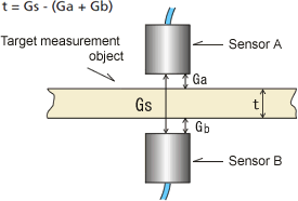
Sensor A/ Sensor B, Measurement object
(Fig.2)
■When measuring conductors or semiconductors
Two sensors are arranged in parallel with a gap (Gs) (calibrated in advance) formed between them and then the gap value is set in the counter. A target measurement object is installed between sensors A and B, and a gap value for each sensor (Ga / Gb) is measured. Then, the thickness (t) of the target measurement object can be obtained by subtracting the gap value from the setting in the counter. (Fig.2)

Note: The sensor case and the opposing conductor are assumed to have equal potential.
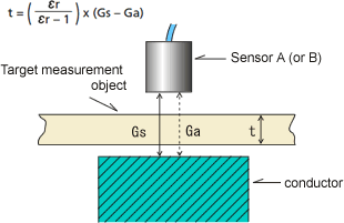
Sensor A (or sensor B), Measurement object, Conductor
(Fig.3)
■When measuring insulators (CL-0300 option)
Specify the space (Gs) between the sensor and the conductor (reference area) at the CL-5600 series. When the target measurement object is inserted between the sensor and the conductor (reference area), the sensor output becomes Ga. The thickness (t) is obtained from the amount of change in the sensor output and the relative dielectric constant εr. (CL-0300 Insulating measurement function is required.) (Fig.3)
εr: Dielectric constant
(When the dielectric constant of a vacuum is 1 the dielectric constant of the target measurement object is referred to as the relative dielectric constant.)
Revised:2010/5/31
