5.Measurement system
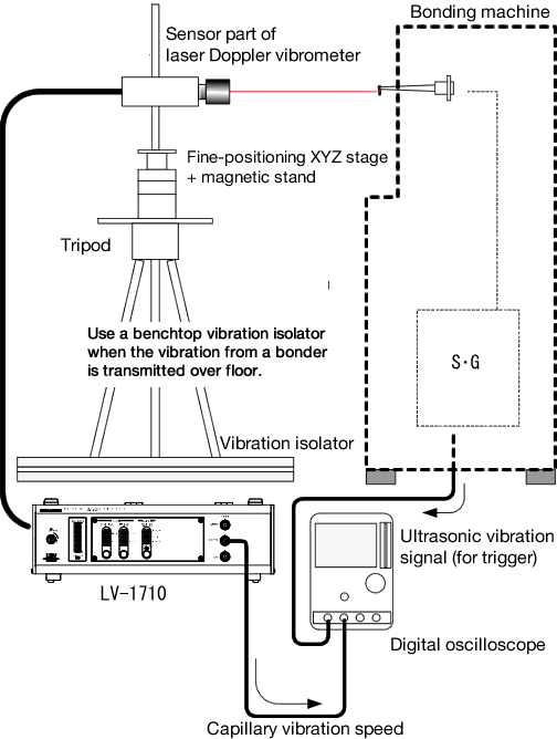
The following shows the system configuration for wire bonding measurement system using the LV-1710 laser Doppler vibrometer and its sensor.

The vibrator has a characteristic that generates a large vibration at a specific frequency (resonance frequency). Because the frequency changes depending on the conditions, the oscillator that drives the vibrator is provided with a feedback circuit to control the frequency.
6.Measurement example
6-1 Vibration measurement during test drive (static check)
The wire bonder has a function to vibrate the tool by inputting the drive signal as a test. If the wire bonder is used for a long time, fatigue will accumulate in the vibrator and horn, and vibration may start differently from the initial state.
When replacing the vibrator or horn, record the vibration value of the horn tip in the initial stage of use.
→ Useful for quantitative maintenance of the vibrator and horn by checking subsequent changes in the vibration value at the tip of the horn.
In particular, measuring whether the vibration amplitude of the actual horn tip or tool increases or decreases in proportion to the increase or decrease of the intensity on the drive signal side is useful data for subsequent maintenance.
→ Provides effective verification method when comparing the performance of each device made by different manufacturer.
For example, when considering changing the transducer, horn, or US oscillator from a bonder manufacturer's genuine product to a specialized manufacturer's product.
6-2 Vibration measurement during tool crimping (dynamic measurement)
The laser Doppler vibrometer is difficult to apply laser light following to the bonding, so measurement cannot be performed in a situation where the wire bonder is continuously bonding (auto bonding). The tool behavior at the moment of bonding is measured by the function (manual bonding) that can be bonded once only once.
Obtaining measurement data with a large rate of change can be said the specific advantage of the laser Doppler method. The creation of “bondability evaluation criteria” for data acquisition must be individually set for bonding machine models, offices, etc. Therefore, it is necessary to acquire and accumulate data periodically and when an event occurs.
As an example, the following phenomenon have been observed.
6-3 Tool vibration mode measurement
Since the tool is also a structure, it has a vibration mode due to the resonance frequency. In particular, when the tool vibrates at 60 kHz or above 100 kHz, measuring the data at multiple points in the length direction allows how the vibration mode changes due to subtle differences in the tool material and shape.
It is generally well known that bondability changes by even slightly changing the tool material and shape. It is also known that bondability is affected by the finish of the tool surface and inner surface and the resonance frequency or vibration mode of the tool. For this reason, laser Doppler vibrometers can provide useful information when developing and validating tools with new shapes and materials.
6-4 Resonance measurement of lead frame
As the integration per chip increases, the lead frame has also become multi-pin or fine pitch. As the lead frame pins are narrowed, the number of cases where the vibration of the pins during bonding adversely affects other pins due to resonance phenomenon etc. is increasing. Those are focused as a cause of defects such as wire breakage and breakage.
There are two possible ways to suppress vibration.
In the case of a wire bonder, vibration is indispensable, so it is necessary to consider how to reduce the propagation of vibration by redesigning the lead frame. The optimum method may change depending on the material and form of the target lead frame, and it is essential to examine structural changes and damping materials while conducting vibration tests.
7.Summary
With regard to ultrasonic fusion in the wire bonding process, analysis and verification by an academic approach has not been performed so far, except for a part.
In actual manufacturing sites, the approach of continuation from past rules of thumb for bonding is still the mainstream, and there are many cases where rules of thumb often avoid falling into difficult situations.
However, it is clear that future uncertainties will continue to increase in wire bonding, such as ICs using new materials, high pin count, narrow pitch, and high speed and high frequency on the wire bonder side.
Academic analysis and verification of ultrasonic welding is expected not only for wire bonder manufacturers but also for device manufacturers that manufacture various devices. As a first step in making these wire bonding processes intelligent, we recommend using a laser Doppler vibrometer.
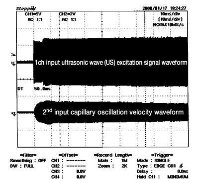
· Printed data

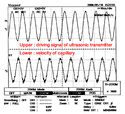
· Zoomed data
