1. Ultrasonic mechanism of wire bonder
The ultrasonic mechanism used for the wire bonder is composed of a bolt-clamped Langevin type vibrator that is a vibration source, a metal horn that increases the vibration amplitude, and a tool (or capillary) that is a Composition. Bonding is performed between a pad or lead frame with a wire and a tool or capillary attached to the tip of the metal horn with screws. The vibration frequency to be applied is generally around 60 kHz, and recently, there are also those with more than 100 kHz.

In order to perform stable bonding, it is necessary to stabilize the vibration amplitude at the tool tip. For this reason, the need to directly measure the vibration at the tool tip is increasing year by year. (The vibration propagated through the metal horn is amplified, and the amplitude of the tool tip is about several μm when there is no load.)
2. Wire bonding and bonding parameters
Bonding parameters
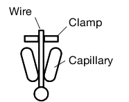
Wire bonding process Example) Ball bonding
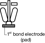
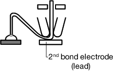
Bonding to the IC pad is called the first bond, and bonding to the lead is called the second bond.
| (1). A ball is formed at the tip of the capillary at the wire end. | (2).The ball is pressed against the pad formed on the chip (bonding surface on the chip) along with the descend of capillary, and bonded. Bonding to an IC pad:1st bonding | (3).The capillary moves onto the lead while wire feeding, and is bonded in the same way. Bonding to a lead:2nd bonding |
|
|
|
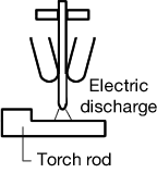
| (4).The capillary is then raised and the clamp is closed to cut the wire. | (5).A high-pressure is discharged to the cut wire end from the torch and the wire end is melted to forms a ball again. | |

|
|
|
-Countermeasure-
・ Increase ultrasonic power or increase oscillation frequency
・ Increase the load
Note) The bonding quality is based on a delicate balance of bonding parameters.
Therefore, inadvertent parameter changes have a bright impact on product yield.
e.g.) Disconnection accidents due to wire peeling or neck breakage
Destruction accidents such as chip side contact pad defects due to overloading
3.Bonding parameter analysis problems
Conventionally, the following methods are used to determine the optimum bonding parameters, monitor the cause of the accident, and investigate.
Various problems have arisen with recent changes in the situation.| 1. Rule of thumb | |
| Advantage | Can be handled in a short time and at a relatively low cost. |
| Disadvantage | Since there is no theoretical or numerical support, it is not always available to deal with new IC varieties as they are. In addition, since the problems at the time of troubles are unknown, the countermeasures are limited, and there is no time when the yield deteriorates once. |
| 2. Tensile strength test with pick gauge | |
| Advantage | Since the tensile strength and bonding strength of the wire itself can be seen, it can be easily inspected. |
| Disadvantage | It is a confirmation of the result, not a cause investigation. Destructive test is performed. |
| 3. Shooting with a high-speed camera | |
| Advantage | Efficient for checking disconnection accidents and peeling |
| Disadvantage | Although it is efficient for confirming the result, it is extremely limited to investigate the cause. In particular, it cannot deal with problems caused by high frequencies such as US oscillation. |
| 4. Measurement of impedance change of Langevin vibrator | |
| Advantage | By installing in each bonder, in-line continuous monitoring are also available. |
| Disadvantage | Unless the rate of change is small and the accident is obvious, the difference will not be known, and there will be almost no introduction effect. |
4. Effectiveness of measurement by laser Doppler vibrometer
An efficient measurement point for verifying bondability is to directly measure the tool tip, pad, or lead frame, which is the action point itself. As a sensor that can measure tools, pads, or lead frames, which has been difficult with the contact method, the laser Doppler vibrometer is currently the mainstream, and efficient results have been obtained.
Laser Doppler vibrometer
:Tools, pads, or lead frames, which has been difficult with the contact method can be measured with
non-contact method.
→Currently the mainstream, and efficient results have been obtained.
Ball bonding tool (capillary)
: A hollow needle with a tapered tip, diameter of about 1.5 mm, and length of about 11 mm.
Material: Generally hard ceramic or ruby.
→It is impossible to attach a contact-type vibration sensor due to the restriction of size.
Triangulation laser displacement meter
: a typical non-contact sensor. Few things can be measured up to high frequencies (60 kHz and above).
→Due to the principle of triangulation, the measurement distance between the sensor and target and the resolution are in a trade-off relation, making measurement impossible.
Advantage and disadvantage of laser Doppler vibrometer
| Advantage | Since the resolution does not depend on the measurement distance, it is easy to quantify with high resolution. Since the measurement is performed in the vicinity of the bonding action point, the change rate of the measurement data is large, and therefore, a difference is likely to occur. In particular, if there is a problem with the vibrator or metal horn, it can be determined relatively easily if there is initial data. |
| Disadvantage | Since characteristics differ depending on the type of IC to be manufactured and the bonder and wire to be used, it is not available to create a reference that will become an industry reference, and it will be handled individually. It takes time to create a reference and is not very efficient. In addition, it is impossible to constantly monitor, and some habituation is required for measurement. |
When other measurement methods are used, the results are generally “unknown” or “no effect” and there is no room for debate. Laser Doppler vibrometer measurement is not “universal” as a test method for bondability, but the best measurement method currently applicable.
Optimal example of a measurement system using laser Doppler vibrometer
Example) Evaluation when changing tools
Tool replacement is usually manually performed. Quantification of the vibration amplitude at the tool tip is important because the bonding state may change depending on the tool mounting position and the tightening torque of the fixing screw. Using laser Doppler vibrometer is efficient means for evaluation during maintenance.
Example) Evaluation of vibration amplitude of transport mechanism
If the holding plate on the transport mechanism is loose, the lead frame will move during bonding. Using laser Doppler vibrometer is efficient means of detecting the loose that contributes to bonding fault.