![]()
![]()
![]()
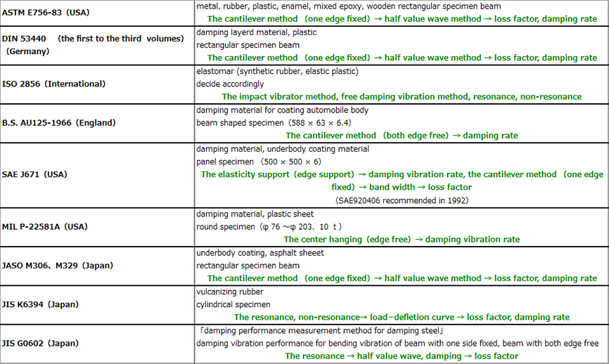
9. Standard for damping performance measurement
There are popular standard in Japan such as JIS K6394, JASO M306, M329m while ASTM E756, BS AU125, dIN 53440, MIL P22581, SAE J671 in worldwide and ISO 2856 as international standard. Recently SAE is partially revised in 1992, USA, JIS G0602 for the laminated damping steel is added in 1994, Japan. There are various methods of evaluating damping performance proposed and/ or recommended in these standards. The cantilever method is one of popular method and adopted in ASTM, dIN and JASO, which is the method using long, narrow rectangular specimen beam, measuring half value width to evaluate damping performance. The two-point support method is adapted in BS, which the vibration damping ratio is measured by the both edge of the short specimen beam supported by knife-edge. The vibration damping ratio is measured by the specimen panel vibrating with the impact excitation and/or single frequency excitation, which is adapted in MIL, SAE. The impedance method is the most popular in Japan, which the middle of specimen beam is vibrated by sin-wave excitation and/or random excitation and the impedance is measured at the driving point to evaluate damping performance. Other than above, there is testing device sold to evaluate damping performance with the relieving phenomenon represented by viscoelastic material. However, the measurement frequency range of these devices is a hundred tens of Hz.
10. Damping performance test method
The popular loss factor testing methods are the cantilever, the central exciting, two-points hanging and two-points supporting. The oberst beam and/or the sandwiched beam are normally used for these testing. The followings show the general characteristics, testing system, error factor and testing result of loss factor for the cantilever and the central exciting method.
|
The characteristics of specimen
| Oberst beam | easy to make specimen data tends to be stable |
| Sandwitch beam | diffcult to make specimen,need spaer resonance frequency tends to be not stable |
| Modified Oberst beam | diffcult to make specimen (errors on specimen) data tends to be not stable |
11. Cantilever method
This method is adapted in dIN, ASTM, JASO, JIS and testing method in SAE.
1. The choice of specimen
Normally it is decided which type of specimen is used according to the Young’s modulus. It is not able to uniquely decide the relation between Young’s modulus of damping material and measurable frequency band. The general relation is as follow:
|
|
3. The accuracy of loss factor measurement with the cantilever method
The loss factor measurement is quite sensitive testing. Even though using the specimen made carefully, the loss factor and/or resonant frequency may vary. It is caused by the minor differences of characteristics of damping material and beam, errors on making specimen. To avoid these errors, it is effective to obtain the average value of loss factor and resonance frequency using 3 or more specimen. The following figure shows loss factor of changes over time. As shown, the loss factor is not stable at the point of changing temperature, in 2 hours later this damping material become stable. The other figure below shows the loss factor and temperature, the loss factor and resonant frequency with the cantilever method.
|
| 1 | The aspect ratio for the specimen dimension, 20:1 is desirable. |
| 2 |
Poor adhesion due to the air mixing on the adhesive surface. Thickness of adhesive material is less than 0.05mm, the elastic modulus is 10 times than damping material. |
| 3 |
defect specimen. Accuracy of dimension. Uneven thickness. The only bending vibration is needed. |
| 4 |
Loose fixing end. Sliding. The increasing damping due to loss of friction, loose fixing, non-linear phenomena most affect the first vibration mode. Therefore, it is better not to adapt the first resonance data. The fixing end should be firmly fixed. |
| 5 | Temperature control. Specimen to be left under same temperature. Adjust within ±1°C. |
| 6 |
Errors of resonant frequency. Appropriate swept speed.
The frequency needs ±1% of accuracy as it affects by square when the elastic modulus is calculated. The vibration should not be added inside non-linear area. (especially single board) (liner range: vibration amplitude proportion to periodical stress and elongation) |
| 7 |
Errors of damping
The mode is not close. No damping of the fixing edge affects. Avoid damping due to non-liner. |
| 8 | Calculation errors |
| 9 |
Adjustment of receiver, exciter.
The distance between electromagnetic receiver and electromagnetic exciter is more than 80 mm to avoid crosstalk caused by electromagnetic leakage. |
| 10 |
Affection of frequency resolution
The desirable number of measurement points within half value width is more than 20. |
5. The choice of device for the cantilever method
The structure of non-contactable electromagnetic exciter which is mainly used for the cantilever method as follow:
|
It is better to wind up a thicker coil (around Φ0.1mm) around 1000 times. It is no meaning to wind up more as it is not able to vibrate with high frequency due to increasing dC resistance and reactance. It is a guide to wind up coil with 100 Ω dC resistances if using the audio amp on the market. In this case, the reactance will be 20mH. The permanent magnet is used under the maximum value of AC magnetic field of electromagnetic exciter.
In case the non-contactable electromagnetic exciter is used with full power, dC field might be not enough. In another case, the small, light specimen is vibrated; dC field might be too strong. Each case the permanent magnet is used as electromagnet (to wind up coil again), then dC voltage apply.
The structure is exactly same as the non-contactable electromagnetic exciter. The same number of windings, wire rods is recommended. In case sending signal into FFT analyzer instead of amplifier, the smaller output impedance is desirable. It is no meaning to wind up narrow wire many times.
The output of this sensor is proportional to velocity, and it is easy to use this sensor as it can measure high frequency. In rare case, it interferes with non-contactable electromagnetic exciter, thus it is careful to use it closely towards non-contactable electromagnetic exciter.
The operation principal is as follow:
|
The accuracy between sensor and target is very good within 0.1%. However, the ratio of sensitive distance between the sensor diameter and target is 10:1. The target is ferroelectrics. It has disadvantage to measure high frequency as displacement sensor, while it has advantage not to interfere with non-contactable electromagnetic exciter.
The piezoelectric type acceleration sensor is most popular. Especially when need to measure the high frequency, the piezoelectric type acceleration sensor is the best in the present. It is most easy to use among other vibration sensors, however, sometimes its weight is issue. In case of measuring loss factor, young’s modulus, the ratio of weight as 100:1 or less is desirable. Also it is careful to handle lead wire not to be damping. Further, the adhesives may cause resonance. The small sensors have low sensitivity, possibility to worsen S/N ratio. The electric charge sensitivity type is 1 pC/ms-2 or more, electric voltage sensitivity type is 1 mV/ms-2 preferable.
It is most excellent response sensor. The distance between target and sensor is more than 100mm, it archives the displacement accuracy to 10-11 m, the frequency more than 1 MHz. Unless the target has perfect reflection, transparent, and it can be measured by any materials. It is most used as the response sensor for the cantilever method. Also it is used as acceleration sensor with impedance head for the central exciting method. The measurement principal is to measure relative velocity of sensor/ target, thus the sensor is firmly fixed on the stable board. In case it is used in thermostatic tank, it is careful to control the upper limit temperature and sudden change of temperature to cause condensation. Another disadvantage is high cost.
|