![]()
![]()
![]()
5. Half value method
When X: displacement, k: dynamic spring constant, c: viscous damping coefficient, m: mass, 1 freedom degree of frequency response function H (jΩ) vibrated by external force F is as follow:
|
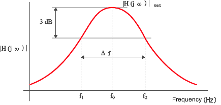
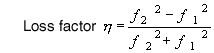
When|H|2 max: max value of amplitude for frequency response function, Ω0 : angular frequency, Ω1 ,Ω2: vibration frequency at the point of half |H|2 max near Ω0, loss factor is as follow:
It is common on actual test to obtain damping performance according to resonance frequency f 0 to read frequency f 1,f 2 which is less 3dB from the peak value of frequency response function.
|
It is useful calculation as
It is calculation without f 0 as
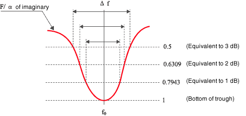
*Sometimes n dB method is used instead of half value method. The correction value is K as follow:
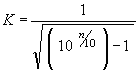 |
K= 1.9652 with 1 dB, K= 1.3076 with 2 dB
*Loss factor obtained from half width method using imaginary number of frequency response function
It is calculated by the above calculation(η = K( f 2 - f 1 )/f 0 )according to the half width value(1/2 not 1/√21) of the imaginary number for the apparent mass (force/acceleration). When all imaginary number of F/a is “minus” and the bottom value is –X to input acceleration into CH A and force into CH B on FFT, f 1 , f 2 is calculated by the following value (if inputting the signal conversely, both imaginary numbers doesn’t correspond):
| Correction value | |
| -X/1.259 (A= 1dB) | K = 1.965 |
| -X/1.585 (A= 2dB) | K = 1.308 |
| -X/2 (A= 3dB) | K = 1.000 |
(It is same correction value as MAG of frequency response function)
|
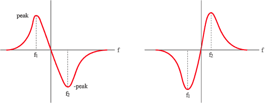
*Loss factor obtained from half width method using real number of frequency response function
|
|
| Real number of apparent mass (F/a) | Real number of stiffness (F/X) |
Either the above numbers
 |
Calculate with this formula
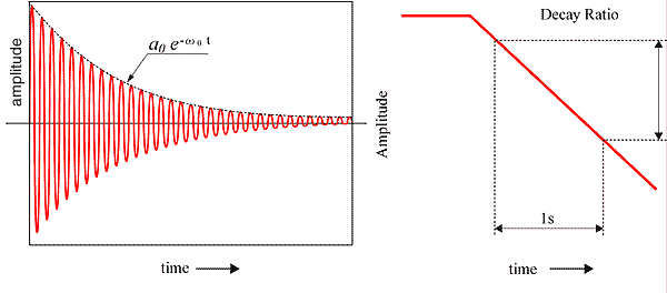
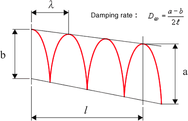
6. Decay ratio method
Affected by the external force, 1 degree of freedom system generates steady state vibration. Without the external force the vibration is getting attenuated, the envelop curve of vibration amplitude represents
d (dB / sec),a0 is fixed number according to initial condition. The attenuation d (dB/sec) for this envelop curve is as
Loss factor is calculated as
*Ω0 = 2 πf0
Loss factor is also calculated to measure T60 (Time for attenuating vibration into 60dB)
It is called as the reverberation time method. These methods are used for small attenuation. To display the damping vibration wave through logarithmic amplifier such as level recorder, it can be represented as the straight line in proportion to envelop curve. The decay ratio is calculated by the slope of straight line. Hilbert transform makes it possible to obtain the decay ratio.
|
The slope of straight line should not be adopted at the right after starting attenuation or at the point of close to the fixed value of the damping vibration wave. In case it is not clear straight line due to the lower level of vibration mode, the filtering takes place.
When the amplitude χn, χn+1 under the damping sin wave, the natural logarithmic value is called as logarithmic decrement, which represents the damping capacity of metallic material.
 |
|
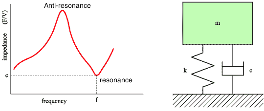
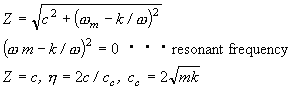
7. Impedance method
Impedance method is useful for the measurement of loss factor under large attenuation. The amplitude for mechanical impedance (F/V) udder 1 freedom degree system as |z|, |z| = c according to 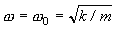 , impedance represents viscous damping coefficient. V means vibration velocity.
Therefore, the loss factor is calculated as
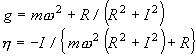
Strictly speaking, the mass, m is calculated through μ∫Wi2 dx ( μ equal to mass per unit length,Wi equal to criterion function under i times vibration mode). The loss factor can be also calculated through mechanical compliance. When 1 freedom degree system is vibrated by force( f = f0 ejwt ), the compliance represents spring as g(1+ η j)
The real part as R, the imaginary part as I, g and η is calculated as
 |
|
Impedance
 |
The actual calculation as follow
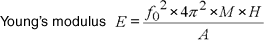 |
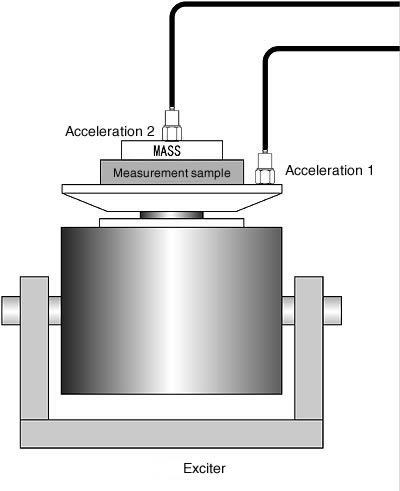
| f0:Resonance frequency (Hx) M :Specimen weight + upper of weight (kg) h :Specimen thickness (m) A :Specimen area (m2) E :Young’s modulus(N/m2) |
|
The loss factor is calculated by half value method using the ratio of acceleration sensor 1 : 2 as above.
8. Non-resonance method
Half value method and decay ratio method is resonance method, which the loss factor is measured at or near the resonance point. While the method here is measured by arbitrary frequency. The edge of long beam is buried in sand, the other edge is vibrated by shaker. Then, the loss factor is calculated by the wave length λ (m) of the standing wave or travelling wave occurred on the beam and vibration damping d (dB/m).
|