![]()
![]()
![]()
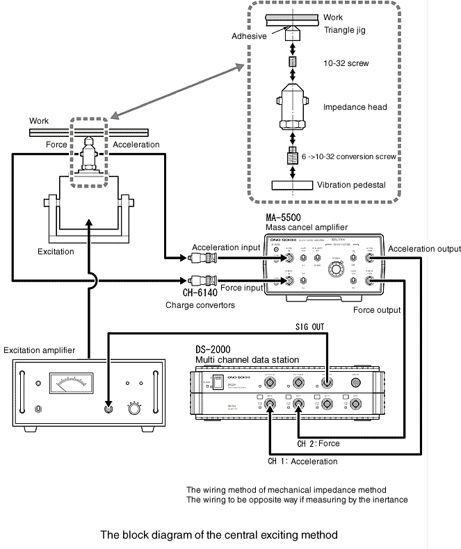
12. Central exciting method
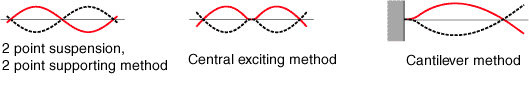
This method is called as mechanical impedance, adopted in JIS standard for the damping steel plate as mentioned but not popular in Euro and USA. The following diagram shows a popular measurement system of loss factor by the central exciting method as well as the cantilever method.
|
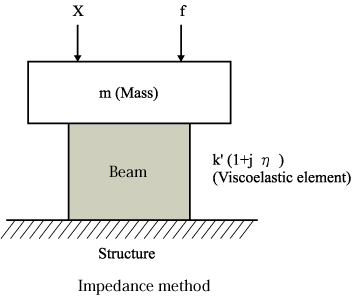
In USA the impedance method is measurement of loss factor with impedance to use a block of damping material.
|
Recently the central exciting is introduced in SAE 920406.
1. Characteristics of central exciting method
*Advantage
Possible to measure the high frequency bands
More flexible dimension of specimen
* Disadvantage
Complicated device
Uncertain impact of supporting point
* Specimen
Rectangle, block-shape
* Testing procedure
Sin wave or random vibration, slow sweep with sin wave
The response can be recorded with frequency response analyzer, FFT analyzer and level recorder. Be sure of frequency resolution, truncation, reading errors.
* Assumption, notes
The specimen dimension is desirable for having an aspect ratio of 20: 1 or higher.
The testing is taken within linear. It is careful to monitor the amplitude of vibration. It is just nice vibration which you can see or not.
Excitation force to be stable.
Bending excitation does not turn to be torsional excitation.
The measurement to be taken near resonance frequency point à within fc / 10
There are 20 or more measurement points desirable within half-value width.
The ideal adhesive width of knife edge is zero, or desirable for 1/200 or less of specimen’s length (0.5mm or less against 100mm specimen)
Mass-cancellation for load cell
With or without mass-cancellation will be affected with 0.03 and less loss factor of specimenZoom analysis to be taken
With or without zoom analysis will be greatly affected with 0.03 and less loss factor of specimen.
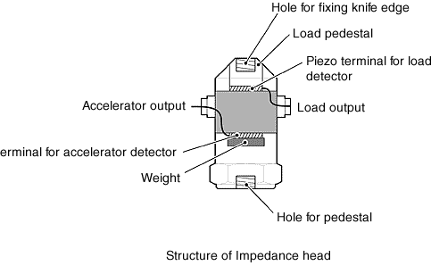
2. Impedance head
The impedance head has the structure which two sensors, the force detector and the accelerometer are integrated into one. It is necessary for the central exciting method as a detector. When the excitation point of impedance is measured, impedance head is fixed on exciter to vibrate specimen. In consideration of placing the impedance head in a thermostat, an electric charge sensitive type of impedance head is desirable. The sensitivity of force detector and the accelerometer is desirable as 100 pC/N or more and 1 pC/ms-2 or more each in considering the weight of specimen is just 100g, excitation force is just 10N. If using a voltage sensitive type of impedance head, it is necessary to monitor the temperature upper limit and the sensitivity of force detector and the accelerometer is desirable as100 mV/N or more and 1 mV/ms-2 or more. Since the fall mode may occur, it is preferable that the height of the impedance head is as low as available. Lead wires are symmetrically drawn in consideration of the balance between the front, rear, left and right, and short connectors are desirable.
|
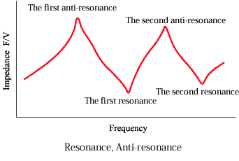
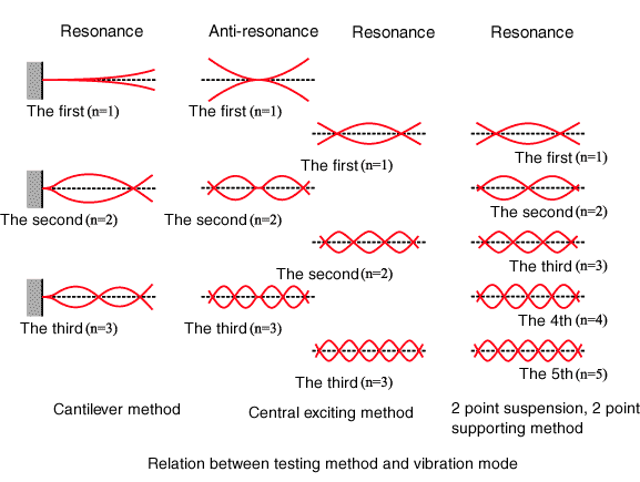
3. Resonance, anti-resonance for the Central Exciting method
When the impedance (F force/ V velocity) is measured in the central exciting method, the resonance frequency and anti-resonance frequency appear alternately as shown in the figure below. At the resonance frequency, the excitation power is very small, and the specimen is vibrated greatly, while at the anti-resonance frequency, the excitation power is great, and the specimen is not vibrated much.
|
|
For example, the center position of the second anti-resonance with central exciting is completely different from the second resonance mode of two-point suspension due to the different boundary condition.
|
The following diagrams show the loss factor measurement results of the damping steel plate with different length of specimen and temperature. As shown, there are differences between resonance frequency and anti-resonance frequency.
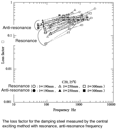
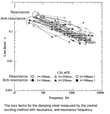
As shown in the figure, the frequency dependence rising to the right is measured greatly at the anti-resonance side, the one dropping to the right is measured greatly at the resonance side. The oberst beam does not show this phenomenon.
4.Error of causes
Problems during the process of making specimen · uneven physical properties, errors of dimension, poor adhesive
Kinds of adhesive materials · thickness of adhesive, unaffected materials by temperature
Control of temperature · uniformity of temperature distribution within the specimen
Need to minimize the energy loss at the supporting point