
![]()
![]()
![]()
DS-0342 Servo Analyzer
(Frequency Characteristics Analyzer)
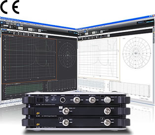
The DS-0342 Servo Analyzer (Frequency Characteristics Analyzer) is a device that measures the transfer function (frequency response function) of control circuits and mechanical structures with high accuracy.
It can measure characteristics (phase margin, gain margin) of the control circuit, resonance frequency of the structure, and impedance, etc.
This is a PC based servo analyzer that pursues usability with the following functions in addition to "easy-to-use operability" and "diversity of graph display".
● Two types of measurement modes are installed: FRA mode and FFT mode
● Maximum number of measurement channel: 4ch (100 kHz unit), 32ch (40 kHz unit)
● Isolation between each channel and signal output
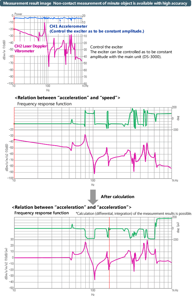
● Control of the exciter is possible
Measurement item:Servo characteristics measurement, impedance characteristics measurement, resonance characteristics measurement, transfer characteristics measurement, acoustic characteristics measurement
Measurement target:DC motor, optical pickup, piezoelectric device, switching power supply, battery, speaker, earphone, etc.
 |
In order to measure the frequency response function (FRF) with high accuracy, the internal channel error of input section is significantly reduced. Amplitude error ±0.05 dB or less (0 to 20 kHz ), ±0.1 dB or less (20 k to 100 kHz) Phase error ±0.3° or less (0 to 20 kHz), ±0.7° or less (20 k to 100 kHz) |
|
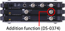
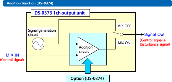
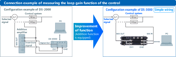
1. Addition function (DS-0374) can be added to the hardware.
* Can be added only to the DS-0373 (1ch 100 kHz band signal output unit) |
 |
2. The output channel and input channel are isolated between units and each input/output. |
||
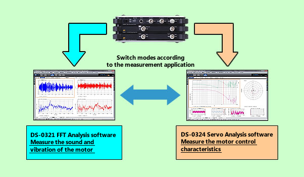
Servo and sound/ vibration analysis
The mechanical control characteristics measurement (servo analysis software: DS-0342) and noise vibration measurement (FFT analysis software: DS-0321) are possible only by switching the mode on the DS-3000 series. For example, camera shake correction control characteristics and motor sound can be measure simultaneously.
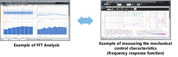
*Click on the image above to enlarge it.
Equipped with useful functions
Damping factor list up function
This is a function to list up the damping ratio (loss factor) by the half-width method at the FRF peak point.
Auto resolution control function
This is a function to increase the frequency resolution near a sharp peak automatically. By getting results with high accuracy in a short time avoids the overlook of a peak.
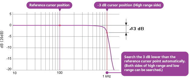
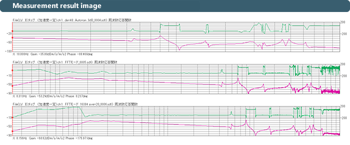
-3 dB auto search function
This is a function to automatically search the -3 dB lower points than the reference value selected with the cursor.
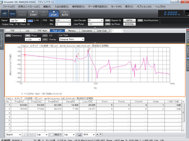
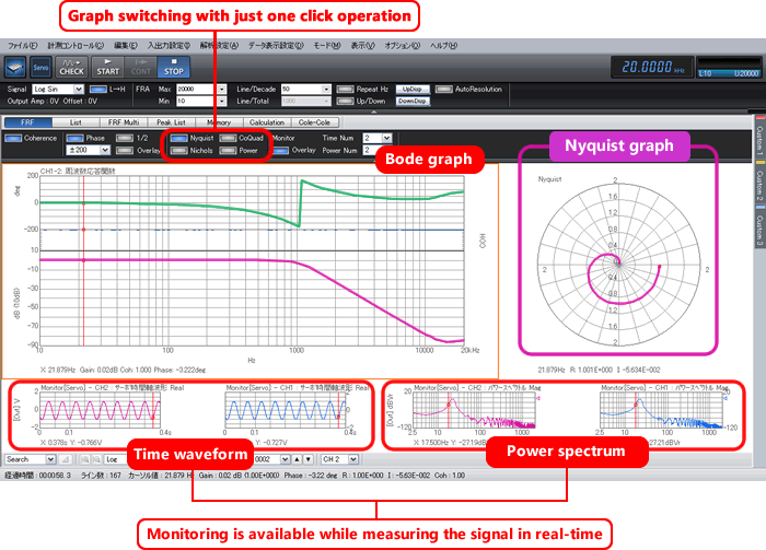
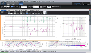
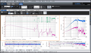
Simultaneous display of various graphs
Frequency response function (FRF) such as Bode graph, Nyquist graph, Co-quad graph, Nichols graph, Cole-Cole plot can be displayed in various ways. Real-time checking of the connection method or abnormality of the system in operation is possible by monitoring the time waveform and its instantaneous spectrum while measuring.
Equipped of two types of calculation mode
This is a method to obtain the gain and phase for each signal frequency.This mode is used for high accuracy and high dynamic range measurement.
FRA mode(Measurement time: 100 seconds)
Log sin sweep excitation
FFT mode(Measurement time: 3 seconds)
Random excitation
The control characteristic measurement and noise vibration measurement are possible only by switching modes.

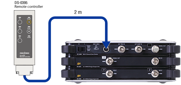
Operation with the remote controller
Measurement start, stop, data storage, etc. are possible without operating the software on the PC. By using the remote controller, you can reduce the load of measurement work by operating from a place close to work or monitoring position.
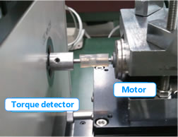
Example 1: Rotation torque control characteristics measurement of small motor
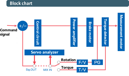
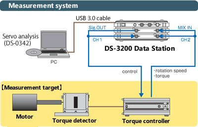
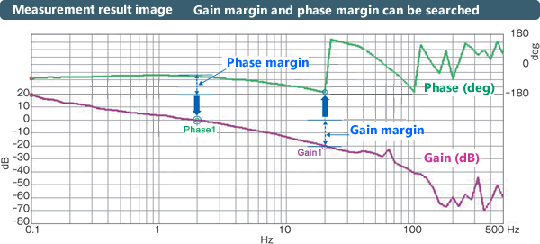
The control circuit (close loop circuit) is incorporated for controlling the rotation speed, torque, etc. of the motor incorporated in various products such as industrial equipment and automobiles. In general, gain margin and phase margin are measured as an evaluation of this control characteristic to evaluate their stability. This evaluation can be done easily and with high accuracy by using the DS-3000 servo analysis system.
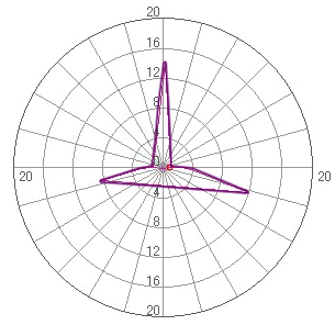
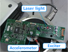
Example 2: Excitation control measurement of electrical equipment substrate using the Laser Doppler Vibrometer
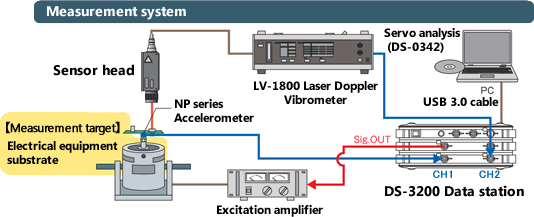
The frequency response function (FRF) such as Bode graph, Nyquist graph, Co-quad graph, Nichols graph, Cole-cole plot can be displayed in various ways. The connection method or abnormality of the system in operation can be checked in real-time by monitoring the time waveform and its instantaneous spectrum while measuring.
Example 3: Secondary battery/ fuel cell battery (for single cell) AC impedance measurement system
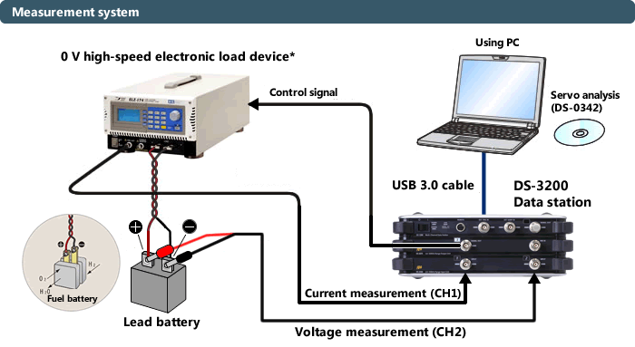
*0 V high-speed electronic load device is a product of Keisoku Giken co., ltd.
<Measurement image Cole -Cole plot>
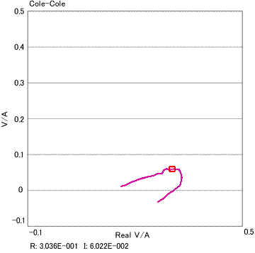
The measurement of AC impedance in actual load state with high accuracy and high-speed is possible by combining the DS-3000 servo analysis system with an electronic load device.
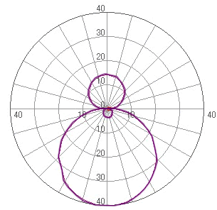
Example 4: Evaluation of the speaker frequency characteristics
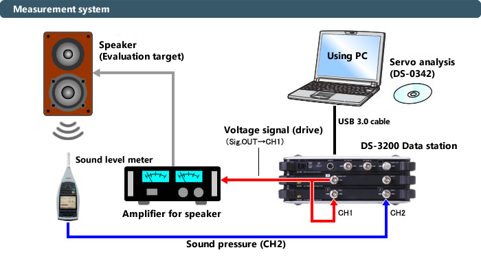
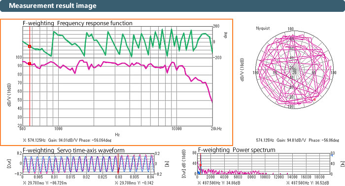
The frequency characteristics of the speaker can be easily measured. Connect the DS-3000 output signal to the amplifier for the speaker and CH1. Measure the speaker sound by the sound level meter or the microphone and connect it to CH2. The DS-3000 incorporates the “Phase rotation calculation correction” function to correct phase rotation from the delay amount between channels.
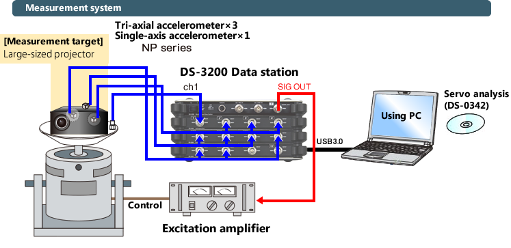
Example 5: Measurement of vibration characteristics of electrical equipment
| Input section | |
| Number of measurement channels | 【When the 100 kHz band input unit is used】 Max. 32ch |
|---|---|
| Coupling | AC/DC With coupling automatic switching function |
| Terminal | BNC (Voltage input/ CCLD switchable) |
| Voltage auto range function | It is possible to measure while optimally selecting the voltage range of each channel according to the level of the input signal automatically. |
| Accuracy between channels | ±0.05 dB or less, ±0.3° or less ( 0 to 20 kHz) ±0.1 dB or less, ±0.7° or less(20 k to 100 kHz) |
| Dynamic range | 140 dB (FRA mode) 90 dB (FFT mode, 100 kHz unit) 110 dB (FFT mode, 40 kHz unit) |
| Signal output function | |
| Number of output channels | 1ch 【When the 100 kHz band input unit is used】 It is isolated from the measurement channel. 【When the 40 kHz band input unit is used】 It is not isolated from the measurement channel |
| Type of output signal | Sine/ Sine sweep (log/ Linear)/ Swept sine/ Random/ Pseudo-random/ Impulse |
| Output voltage | Combine the offset voltage and amplitude: Max. ±10 V (Peak), Min.±10 mV or less |
| Offset voltage | Mode that always outputs even in the stop state |
| Amplitude output taper | Upward and downward taper (1 ms to 10 s) |
| Measurement start delay | Set delay time from signal output until measurement (1 ms to 10 s) |
| Switching of output impedance | 50 Ω, 0 Ω switchable |
| Measurement mode (FRA mode) | |
| Measurement frequency range | 10 mHz to 100 kHz |
| Frequency resolution (log sweep) | 10, 20, 40, 50, 80, 100, 120, 160, 200, 250, 300, 320, 400, 500/decade |
| Frequency resolution (linear sweep) | 100, 200, 400, 500, 800, 1000, 2000, 2500, 4000, 5000/ entire band |
| Number of averaging | 1, 2, 3, 4, 5, 6, 7, 8, 9, 10, 20, 25, 30, 40, 50, 60, 80, 100, 120, 150, 180, 200 times and arbitrary number or times |
| Frequency range division setting mode | Measurement can be made by dividing the measurement frequency range up to 10, changing the number of additions and the signal output level. |
| Auto resolution control function | The function to automatically optimize the decade of each frequency band so that the characteristics of the entire frequency range can be observed with high accuracy. |
| Measurement mode (FFT mode) | |
| Number of FFT points | 512, 1024, 2048, 4096, 8192, 16384, (32768, 65536) point *In parentheses only when signal output is random noise |
| Frequency range (single range) | 100 k, 50 k, 25 k, 20 k, 10 k, 5 k, 4 k, 2.5 k, 2 k, 1 k, 500, 400, 200, 160, 100, 80, 50 Hz |
| Frequency range (pair range) | Hi range: same as a single range Low range: 1/5, 1/10, 1/20, 1/50, 1/100 of Hi range |
| Number of averaging | 2, 5, 10, 40, 50, 60, 80, 100, 120, 150, 200, 250, 300, 400, 500, 600, 800, 1000, 1200, 1500, 1800, 2000 times |
| Frequency resolution enlarge function | It is possible to re-measure by generating a sine wave whose frequency resolution is 20 times finer than frequency resolution at the time of measurement. |
| Calculation function | Frequency axis differential calculus function (first differential, second differential, single differential, double differential)
Four arithmetic function |
| Display | |
| Display of frequency response function | Co-quad graph (horizontal axis: frequency/ vertical axis: real part and imaginary part) |
| Bode graph (horizontal axis: frequency/ vertical axis: gain and phase) | |
Nyquist graph (horizontal axis: real part/ vertical axis: imaginary part)(Logarithmic axis display of amplitude is available) |
|
| Nicols graph(horizontal axis: phase/ vertical axis: gain) | |
| Cole-cole plot | |
| Display mode | FRF mode (three screen display) 1. FRF (gain/phase), COH (ON/OFF of the display is available) 2. Either of Nyquist, Co-quad, Nicols or SPEC (1, 2ch overwrite) 3. TIME, instantaneous spectrum
(Overlapping display and selecting channel are possible) |
List mode(dual screen display) 1. Measurement condition 2. List of all measurement data of No./ Frequency/ FRF gain/ FRF phase/ COH/ FRF real part/ FRF imaginary part/ SPEC 1/ SPEC 2/ Number of addition
|
|
Peak list mode(Dual or three screen display) Frequency, gain, and transportation are listed on the FRF bode graph display in three ways. 1. Peak point of the gain (auto search) 2. Arbitrary point 3. Gain margin and phase margin (auto search) 4. Damping factor list up function |
|
Memory mode 1. FRF current condition 2. List of the stored waveform 3. Overlapping display of the waveform which selected in 2. (max. 20 screens) |
|
Calculation screen (four screen display) 1. Current FRF 2. Stored FRF 3. Waveform after four arithmetic operation/ calculus of 1. and 2.
Waveform after open and close loop conversion of 1. and 2.
4. Nyquist graph and Nicols graph after the calculation results of 3.*Display of the waveform after calculation is available |
|
| Display function | Phase unwrap display Search delta function |
*Frequency response function (FRF), Coherence function (COH), Power spectrum (SPEC), Time-axis waveform (TIME)
*There are restrictions on the max. analysis frequency range and number of lines depending on the number of channels in use.
| Option function | |
| ■ Addition function (DS-0374) | The option to add the addition input terminal for adding disturbance noise in the hardware main unit. (Note: Only with 1ch 100 kHz band signal output unit (DS-0373)) |
|---|---|
| General information | |
| Power supply | 100 to 240 VAC, 15 VDC/25 to 95 VA (When 15 VDC) |
| Accessory | Instruction manual, AC adapter, Cable for AC adapter |
| Standard | Conforming to CE marking |
| Others | |
■-3 dB auto search function ■Group delay ■Cross conversion function for open loop to close loop ■Automatic search function for gain margin and phase margin |
|
| Interface | Required to be equipped with an USB 3.0 interface. USB 2.0 can also be used, (USB 3.0 is faster than USB 2.0) |
|---|---|
| OS (Operating System) | Microsoft® Windows® 10 version 21H1 SAC Pro(64-bit) Other editions such as Enterprise, Education, Enterprise 2019 LTSC, etc. need to be discussed individually. |
| Applicable .NET Framework |
.NET Framework 3.5.1 |
* Note that the DS-3000 Multi-channel data station does not work properly when the compatibility mode or Microsoft® Virtual PC is used.
* Note that the DS-0342 (Servo analysis) does not support DS-0399 ONO-LINK3 (USB).
Required Specification of a PC
| CPU | Intel® CoreTM i5 processor or more (recommended 2 GHz or more) |
|---|---|
| Memory | 4 GB or more |
| Hard disk | 1 GB or more free space |
| Optical drive | Optical drive that DVD-R and CD-R can be read at the time of installation and updating. |
* Even with a PC that conforms to the operating environment, this system may not operate properly due to the physical shape, influence of other installed software or peripheral devices.
Combination Example
2ch Servo analysis set (for 100 kHz)* |
|
◆DS-3200 Main unit |
* Combination of the DS-0366 (2ch, for 100 kHz band input unit) and the DS-0373 (1ch, for 100 kHz band signal output unit) can be changed to DS-0364 (4ch, for 40 kHz input unit) and the DS-0371 (signal output module for 1ch, 40 kHz unit). (In this time the unit is corresponding to 40 kHz.)
4ch Servo analysis set (for 100 kHz) |
|
◆DS-3200 Main unit |
| Model name | Product name |
|---|---|
| DS-3200 | Main unit |
| DS-0366 | 2ch 100 kHz band input unit |
| DS-0373 | 1ch 100 kHz band signal output unit |
| DS-0374 | Addition function option (built-in the DS-0373) |
| DS-3202 | 2ch 40 kHz main unit (2ch standard set: DS-3200 and DS-0362) |
| DS-3204 | 4ch 40 kHz main unit (4ch standard set: DS-3200 and DS-0364) |
| DS-0362 | 2ch 40 kHz input unit (for channel addition) |
| DS-0364 | 4ch 40 kHz input unit (for channel addition) |
| DS-0371 | 1ch Signal output module for 40 kHz unit (built-in) |
* 100 kHz unit and 40 kHz unit cannot be used together.
* 100 kHz units cannot connect each other.
* The maximum configuration of the 100 kHz unit is "DS-3200+(DS-0366×2)+(DS-0373×2)" (input 4ch, output 2ch).
* DS-0373 can be added only in combination with the DS-0366.
* DS-0374 corresponds to DS-0373 only and is built-in the main unit.
* If the number of units is 5 or more including the main unit, a large AC adapter is required as an option.
* Additional operation fee is required for adding the hardware after delivery.
* In the 40 kHz unit configuration, install the FAN on the rear of the unit when the number of units is 5 or more including the main unit.
In the 100 kHz unit configuration, install the FAN on the rear of the unit when the number of units is 4 or more including the main unit.
* Signal output function is necessary for the DS-0342 (Servo analysis)
ONO-LINK 3 Cable-Unit Connecting Interface (exclusive for DS-3100)
| Model name | Product name |
|---|---|
| DS-0396 | ONO-LINK ONO-LINK 3 (for desktop PC, PCIE Express) |
| DS-0397 | ONO-LINK 3 (for notebook PC, PC card) |
| DS-0398 | ONO-LINK 3 (for notebook PC, Express card) |
| AX-9031 | I/F cable for ONO-LINK 3 (1.5 m) |
| AX-9032 | I/F cable for ONO-LINK 3 (3 m) |
| AX-9033 | I/F cable for ONO-LINK 3 (10 m) |
AX-9034  |
I/F cable for ONO-LINK 3 (20 m) |
*DS-0399 ONO-LINK 3 (USB) is not applicable to the DS-0342 (Servo analyzer)
Software
| Model name | Product name |
|---|---|
| DS-0342 | Servo analysis function |
| DS-0321 | FFT analysis function |
| DS-0321L | FFT analysis function (offline license type) |
| DS-0350 | Recording function |
| DS-0322 | Tracking analysis function |
| DS-0323 | 1/1, 1/3 real-time octave analysis function |
| DS-0323L | 1/1, 1/3 real-time octave analysis function (offline license version) |
| DS-0324 | 1/N real-time octave analysis function |
* Each software can be used for both 40 kHz unit and 100 kHz unit (Hardware).
Revised:2017/03/31