
![]()
![]()
![]()
![]()
Features
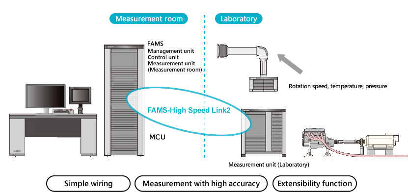
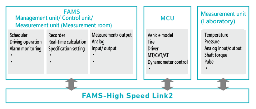
FAMS-R5 uses the system with high-speed communication, FAMS High-Speed Link2, to share data with each unit.
Sensors can be directly connected to the measurement unit in a laboratory.
Simple wiring and highly accurate measurement can be achieved.
By adding the MCU that can calculate the control model with MATLAB/Simulink, it also supports the simulation bench.
Fuction configuration
Application example
Various testing system can be build up based on the FAMS-R5 automatic drive measurement system. (Click below title for more details.)
*FAMS-R5:Flexible Automatic Measuning System - Release5
*FAMS(Flexible Automatic Measuring System)is a trademark of ONO SOKKI.
Bench test support application for FAMS-R5
This is application software to support efficiency improvement in the increasingly complex vehicle bench tests. This software describes test flows in flowchart and therefore makes test customization easier. It is so flexible and expandable application software that it enables advanced automatic driving, such as controlling external devices as well as describing a driving pattern.
![]()
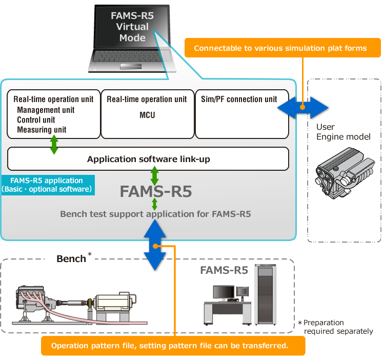
FAMS-R5* Virtual mode
*FAMS-R5 : Flexible Automatic Measuning System - Release5
Feature
More efficient and productive system operation
You can build a bench system virtually with one PC, leading to the effective utilization of bench system.
Regardless of the operating condition of the bench, test items of FAMS-R5 such as execution of operation pattern can be reproduced at the office etc.
For more speedy and effective development
FAMS-R5 can connect with a sample model, such as a user-created engine model, on a PC. Test setting, validation and pre-matching of test operations can be performed on the desk, leading to faster development.
Easy setting reproduction through files
Various setting functions and operation patterns that have been set and checked on the desk can be output to a file. The settings are reflected on the bench just by copying the setting file to the bench.
System configuration
Function list
| FAMS management unit | ||
| Program driving setting/ Execution function | ||
|---|---|---|
| Driving pattern setting Number of setting steps (up to 100,000 steps) | ||
| Combination program (up to 999) | ||
| Number of command item (up to 32 ch), mark signal | ||
| Step up condition | ||
| Step up alarm, program monitor, continuous step driving | ||
Alarm system setting/monitoring/display |
||
| Upper/Lower limit, external contact, map, data freezer | ||
| FAMS control unit | ||
| Specification setting | ||
| Specification setting, dynamo specification, control condition, etc. | ||
| Control function | ||
| Dynamometer control, throttle control | ||
| Transient mode predictive control function | ||
| Change controller, temperature control, etc. | ||
| Application software | ||
| General-purpose steady testing, general-purpose transient testing, mapping driving function | ||
| Road load setting control function | ||
| FAMS measurement unit | ||
| Data measurement/ calculation function | ||
| Analog measurement (temperature, pressure, analog) Digital measurement (DIO, pulse) | ||
| Real-time calculation, moving average processing | ||
| Data processing | ||
| Application based on exhaust emission data processing (for legal mode requirement) | ||
| Application for special processing | ||
| ECU monitor communication, CAN communication device, growth chart | ||
| External device interface | ||
| Exhaust emission analyzer, tunnel equipment, smoke meter, opasi meter, | ||
| micro soot sensor, fuel consumption meter, wattmeter, etc. | ||
Please contact us for details on functions such as applicable legal testing mode.
Revised:2020/10/16