
![]()
![]()
![]()
Various products and machines around us such as home appliances and automobiles incorporate a motor as a drive source. As an important component of products and machines, motor can be required for high-performance and high-efficiency and downsizing, lightening to improve the performance of products and machines as well as low vibration and reduced noise.
However, most of current motors have a problem called uneven torque, which prevents high-efficiency and causes vibration, noise. One of the causes of this problem is a phenomenon called cogging torque. It is a rugged resistance that can be felt even when no current is flowing due to the action of the iron core and permanent magnet, which are components of the motor. By reducing this cogging torque, motor output efficiency and noise / vibration reduction can be achieved. In recent years, it has been focusing on as an important factor for measuring motor performance.
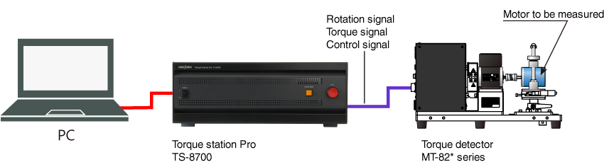
We use here TS-8700 Torque station Pro to measure cogging torque to connect the shaft of the motor to be measured to the motor torque detector MT-82 * series, and perform measurement while rotating the shaft at a very low speed with the geared motor inside the detector. The geared motor inside the detector can be controlled at a constant rotation between 0.5 and 5 r/min (2 to 15 r/min for some models), it enables stable and highly reproducible measurements.
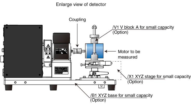
Enlarged view for Detector (motor to be measured)
System configuration
| Type | Name | Remarks | |
|---|---|---|---|
| 1 | TS-8700 | Torque station pro | |
| 2 | MT-82*series | Torque detector | MT-82M*: torque capacity 0 to 2 mN · m to 0 to 20 N · m, 13 models MT-82T*: torque capacity 0 to 50 mN · m to 0 to 20 N · m, 9 models |
| 3 | /X1(Option) | XYZ stage for small capacity | XYZ stage for small capacity |
| 4 | /V1(Option) | V block A for small capacity | V block used for the measurement of small capacity torque (Φ30 to 60) using XYZ stage (/X1),coupling is user preparation. |
| 5 | /B1(Option) | XYZ base for small capacity | Base to attach a target with XYZ stage (/X1) and V block (/X1) |
Example of analysis
Points
Note to avoid waveform with zero point at the center due to bearing loss.
The entire graph shows waviness with one rotation, one cycle when the centering is too much shifted.
In this case, re-measure by re-centering or evaluate by the latest peak value to shorten time of centering.
The control rotation speed (r / min) is set according to the motor to be measured and the actual values obtained from the customer. There is no reference data, however, 1 r/m is mostly used.
Depending on the setting speed, there may be a difference in the result data. When rotating fast, the peak becomes gentle. Since the rotation speed is slow, the loss does not increase by rotating faster.
Revised:2019/11/29