
![]()
![]()
![]()


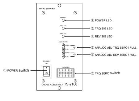
1.Front panel
2.Rear panel
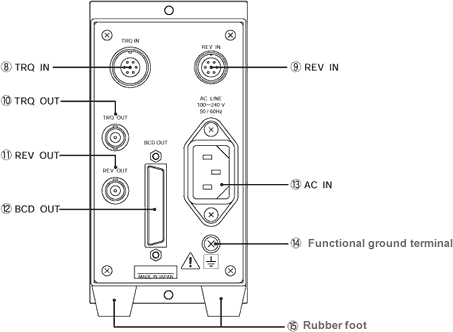
(8) TRQ IN
Connector to input the signal from the torque detector. Applicable connector: TRC116-12A10-7M10.5 (Made by TAJIMI ELECTRONICS.) Please use the exclusive cable which is attached to the torque detector.
| Pin | Signal name |
|---|---|
A |
SIG1 |
B |
SIG2 |
C |
SIG1 COM |
D |
SIG2 COM |
E |
NC |
F |
SIG COM |
G |
NC |
(9) REV IN
Connector to input the signal from the rotation detector. Applicable connector: R03-PB6M (Made by TAJIMI ELECTRONICS.) Please use the exclusive rotation detector (MP-981 Magnetoelectric Detector) and exclusive cable (MX-8105 5 m).
| Pin | Signal name |
|---|---|
A |
SIG |
B |
NC |
C |
12 V |
D |
FG |
E |
SIG COM |
F |
12 V COM |
(10)TRQ OUT
Analog voltage output connector for the torque data.
Applicable connector: C02 type (BNC) connector
(11) REV OUT
Analog voltage output connector for the rotation data.
Applicable connector: C02 type (BNC) connector
(12) BCD OUT
BCD output connector for the torque/rotation data. Data and polarity are positive logic. Hold, busy and print control are negative logic. All of them are open collector output.
Applicable plug: DX40-50P (Made by Hirose electric co., ltd.)
Plug cover: DX-50-CV1 (Made by Hirose electric co., ltd.)
The signal cable is made to order.
| Pin No | Signal name | Pin No | Signal name | ||
|---|---|---|---|---|---|
| 1 | Data output | 1×100 | 26 | Data output | 2×101 |
| 2 | (Torque part) | 2×100 | 27 | (Rotation part) | 4×101 |
| 3 | 4×100 | 28 | 8×101 | ||
| 4 | 8×100 | 29 | 1×10² | ||
| 5 | 1×101 | 30 | 2×10² | ||
| 6 | 2×101 | 31 | 4×10² | ||
| 7 | 4×101 | 32 | 8×10² | ||
| 8 | 8×101 | 33 | 1×10³ | ||
| 9 | 1×10² | 34 | 2×10³ | ||
| 10 | 2×10² | 35 | 4×10³ | ||
| 11 | 4×10² | 36 | 8×10³ | ||
| 12 | 8×10² | 37 | NC | ||
| 13 | 1×10³ | 38 | NC | ||
| 14 | 2×10³ | 39 | NC | ||
| 15 | 4×10³ | 40 | NC | ||
| 16 | 8×10³ | 41 | NC | ||
| 17 | NC | 42 | Torque polarity output [-] | ||
| 18 | NC | 43 | Torque polarity output [+] | ||
| 19 | NC | 44 | NC | ||
| 20 | NC | 45 | NC | ||
| 21 | Data output | 1×100 | 46 | NC | |
| 22 | (Rotation part) | 2×100 | 47 | Hold input | * |
| 23 | 4×100 | 48 | Busy input | * | |
| 24 | 8×100 | 49 | Print command output | * | |
| 25 | 1×101 | 50 | Common | ||
Above * marks are negative logic output. NC stands for non-connection.
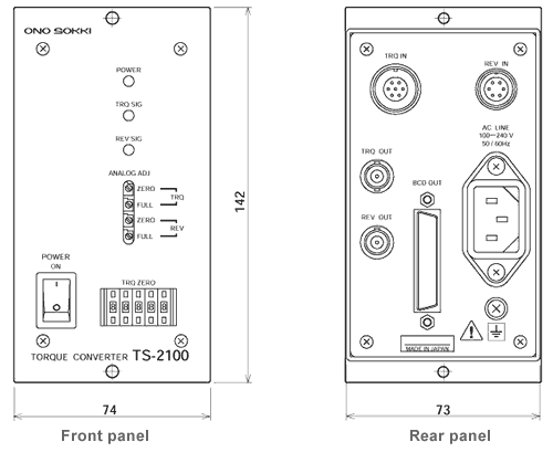
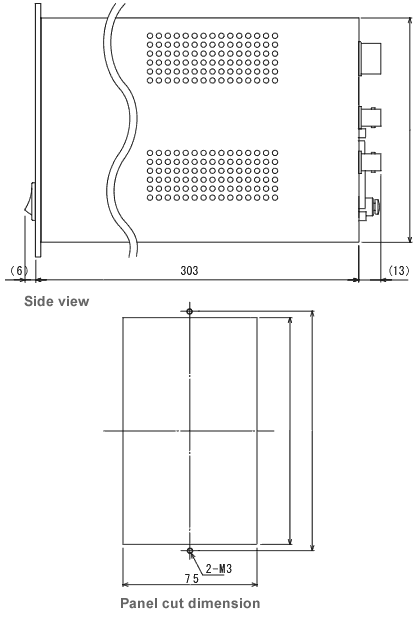
3.Outer dimensions
Revised:2002/03/15
