
![]()
![]()
![]()


Select a coupling suitable for the torque capacity. Recommended couplings are noted in the torque meter catalogue and torque detector manual. See also the Torque meter FAQ 「Coupling selection and centering accuracy」
Any eccentricity affects torque measurement, and may result in abnormal vibration/noise and consequent failure. Although a certain amount of eccentricity is permitted, the SS series centering should ensure that eccentricity is limited to 5/100 mm (T.I.R :Total Indicator Reading, difference between maximum and minimum measured values). The centering accuracy is described in the torque detector manual.
As shown in the following diagram, centering of the torque detector is conducted while checking eccentricity. The shaft centers of the torque detector and the motor are aligned by inserting shims between the torque detector and the mounting frame to adjust height and left-right. See the coupling manufacturer’s manual, etc. for installation details. Imbalance at high-speed will result in vibration. Follow the advice of persons experienced in the installation of rotating machinery.
The following provides an outline of coupling installation (Contact the coupling manufacturer for details).
| 1. | Verify that the shaft and hole are free of burrs, and check that the key can be fitted properly between the shaft and coupling hub. |
| 2. | Fit the coupling hub to the shaft. |
| 3. | Adjust so that the machine and torque detector are able to be joined with the distance between shafts according to the coupling specifications. |
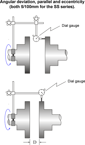
| 4. | Adjustment of angular deviation Fix a dial gauge to one half of the coupling hub and place the dial gauge measurement probe on the coupling hub surface (measured side) of the other half. Rotate the hub to which the dial gauge is fixed by 360°, and reset the display to zero at the point of the minimum reading on the dial gauge. Rotate the same half of the hub by 360° again, and insert shims between the torque detector and the frame to adjust inclination so that dial gauge runout is a maximum of 5/100 mm (T.I.R) (SS Series). |
| 5. | Adjustment of parallel and
eccentricity Fix a dial gauge to one half of the coupling hub and place the dial gauge measurement probe against the outer periphery of the other half. Rotate the hub to which the dial gauge is fixed by 360°, and reset the display to zero at the point of the minimum reading on the dial gauge. Rotate the same half of the hub by 360° again, and insert shims between the torque detector and the frame to adjust height and left-right so that dial gauge runout is a maximum of 5/100 mm (T.I.R) (SS series), and temporarily lock the torque detector in place. Check angular deviation again. |
| 6. | Assemble the coupling and connect it to the shaft. |
| 7. | Lock the torque detector firmly in place. |
| 8. | A knock pin may be installed in the torque detector frame for use in maintenance. |
 |
|
Revised:2014/04/14
