
![]()
![]()
![]()


Caution
The ripple phenomenon (please refer to the figure 1) There is a lower limitation for the measurement due to the ripple phenomenon. The ripple phenomenon caused by the lower rotation speed of the integration type FV conversion circuit. The lower limitation of the measurement is changed depending on the setup of the frequency range or the response, but please process the measurement with 20Hz or more as a guide.
For the LG-916 or LG-930 Photoelectric detector, the ripple increases because of the low frequency signal if you use only 1 reflective mark. Please pay attention to the lower limit of the measurement range. When you use only 1 reflective mark, please use it with around 1000 r/min or more rotation speed. <Ripple phenomenon>
• The circuit for the analog output is different one for the digital display, so there is no influence from the setup conditions of digital display.
• The analog output terminal is able to output the voltage (10 V/ frequency range) and electric current (4 to 20 mA/ 0 to frequency range) at the same time. However, if you use the voltage output and electric current output at the same time, it needs to complete the available condition.
Please refer to the installation manual for the details.
Measurement condition
The measurement condition is as follows.
|
Setup of analog output
1. The selection of the frequency range
Use the following expression to find the maximum frequency.
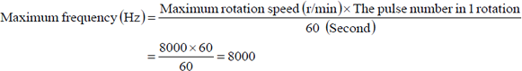
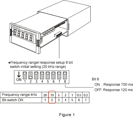
2. Setup the frequency range of [10 kHz] which can cover the maximum frequency
Setup the [bit 2: ON] and [bit 1, 3, 4, 5, 6 and 7: OFF] as a figure 1. You can select the frequency range from 7 kinds which are 20 kHz, 10 kHz, 5 kHz, 2 kHz, 1 kHz, 500 Hz or 200 Hz. When the selected frequency range becomes F.S (full scale) and the frequency of the input signal and frequency range become the same value, 10 V of voltage and 20 mA of electric current are outputted.
(Example) When the setup of 10 kHz range
When the input signal is 10 kHz, the voltage output is 10 V and
the electric current output is 20 mA. Moreover, when there is no
signal, the electric current is 4 mA.
The digital display value is corrected by the multiplier setup
value. Thus, please notice that you need to convert the value to
readout the voltage output as the display value.
3. Setup of the response
Setup the response (response function) with the bit 8 shown as a figure 1. The ripple is changed by the setup of [bit 8: OFF (120 ms)] or [bit 8: ON (700 ms)]. Please refer to the following diagram 1 for the amount of the ripple. The signal output of ON (response 700 ms) setup is smoother than OFF (response 120 ms) setup. If you use under the low frequency range condition or you need the average output, please setup with [bit 8: OFF (700 ms)]
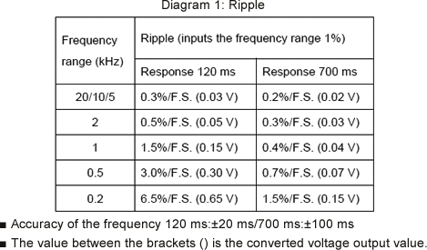
How to read the diagram
(Example)The ripple for the frequency range 10 kz, response 120 ms and 0.3%/F.S. (0.03 V) setup.
Frequency range 1%= 10 kHz × 1%=100 Hz
When the input signal is 100 Hz, the ripple is 0.03 V (10 V × 0.3%=0.03 V). If the frequency becomes smaller than 100 Hz, the ripple becomes larger than 0.03 V.
4. Specification and wiring for the analog output
(4-1) Analog output specification
| Frequency range | 20 kHz, 10 kHz, 5 kHz, 2 kHz, 1 kHz, 0.5 kHz and 0.2 kHz |
|---|---|
| Linearity | ± 0.3% /full scale |
| Output voltage | 0 to10 V (load 1 kΩ or more) for each frequency range |
| Output electric current | 4 to 20 mA (load 500 Ω or less) for each frequency range *It is possible to output the voltage and electric current at the same time if the voltage load is 100 kΩ or more. |
| Output ripple | It depends on the frequency range and response. |
| Output control | Around ± 5% /full scale (voltage) Around ± 3% /full scale (electric current) |
| Zero setup accuracy | ± 0.5% /full scale (voltage output, room temperature) ± 0.3% /full scale (electric current output, room temperature) |
| Zero drift | ± 0.01% /full scale /°C |
| Span drift | ± 0.025% /full scale /°C |
| Response | Select 120 ms ± 20 ms or 700 ms ±100 ms |
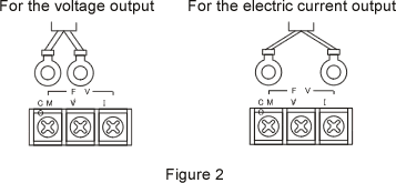
(4-2) Wiring method
The wiring is shown in the following figure 2. Please use the shielded cable and make sure to ground the shield at the connection device.
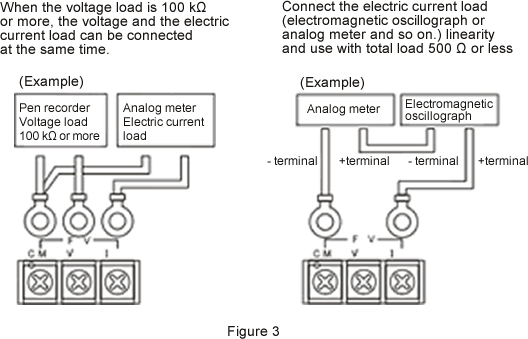
(4-3) Use the voltage output and electric current output at the same time
If you connect the voltage output and electric current output at the same time, make sure to complete the conditions of the input resistance of the connection device shown in the following figure 3.
Revised:2013/03/16
