
![]()
![]()
![]()


When you detect rotations using photoelectric detectors such as the LG-916 and the LG-930 with a piece of reflective mark on a rotating shaft, if the rotational speed is low, the number of pulses per second in a signal will be small. As a result, the output voltage will be as the questions above because the frequency of the signal will be extremely low among the frequency range of the FV conversion circuit.
Description
The TM-2130 and the FV-1100 utilize a FV conversion circuit (frequency-to-voltage conversion circuit) for converting an input signal into a voltage in proportional to the frequency of the signal.
A block diagram of the FV conversion circuit is as follows.
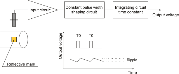
An integrating circuit is charged when the frequency of input pulses is high, and discharged when it is low. If the frequency of the input pulses becomes higher, the number of charging times increase and the charging time in total becomes longer; therefore the output voltage increases. To the contrary, when the frequency becomes lower, the discharging time will be longer than the charging time and the output voltage decreases. The smaller the time constant is, the faster the time of charge-discharge becomes and the wider the gap of charge-discharge voltage per 1 pulse (ripple) becomes. Also, the ripple is very small when the input frequency is high, however, the lower the frequency is, the larger the ripple becomes.
The photoelectric detectors such as the LG-916 and the LG-930 output same number of signals as the reflective marks attached on the rotating shaft per 1 rotation. Therefore, the input frequency tends to be low and the output voltage tends to be as mentioned in the question. You should calculate an input frequency from the range of rotation number which you would like to detect, and confirm that it will be more than 10% of the frequency range of the FV conversion circuit.
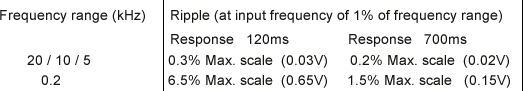
Follows are an excerpt of the quantity of the output voltage ripple at the input frequency is 1% of the frequency range. The whole table is in the TM-2130 instruction manual.
Revised:2009/07/21
