Technical Report


What is sound level meter?


10-7 Information that should be recorded

In addition to the results of sound measurement, the following information should also be recorded.

(1) Methods for measurement

(a) Types of sound level meter; methods for measurement or calculation
(b) Reference time interval, measurement time interval, Sampling intervals, times, etc. (if sampling is used)

(2) Conditions for measurement

(a) Atmospheric conditions: Wind direction, wind velocity, rain, temperatures at ground level and other altitudes, atmospheric pressure, relative humidity

(b) Types and conditions of ground surface, variability and other properties of sound sources, with or without specific noise and, if "with," its characteristics, direction, etc.

(c) Points of measurement (position, height)


10-8 Annex 1 (Rules): Collection of acoustic data for appropriate use of land

NOTE:

Annex 1 (Rules) of JIS Z 8731:1999 is a translated version of ISO 1996-2:1983

(1) Overview

The rules specify methods for describing environmental noise in specific areas as well as specific measuring methods as a means of evaluating the appropriateness of land use that takes into account the noise both existing at present and expected in the future. The provisions are expected to be adopted by the Environmental Impact Assessment Act. Areas in which either long-term average sound level or long-term average rating level is located between a certain range are color coded and shown as 5 dB-segment noise level zones in a contour line format on the local map.

(2) Collection of basic data

The following basic data needs to be collected.

(a) Local topography

(b) Statistical annual data on wind direction, wind velocity, rainfall and temperature as part of information on the status of the local residents and the surrounding areas

(3) Acoustic data

Representative values in rating level, long-term average sound level and long-term average rating level for specific points of measurement should be obtained for each time interval while taking into consideration the characteristics of the noise sources and the points of measurement. Percentile sound pressure level should be obtained to enable evaluation of the noise level distribution.

(3-1) Positions and numbers of points of measurement

Outdoor points suitable for describing the environmental noise in question are selected and indicated on the map while taking into consideration spatial resolution. For example:

(a) The entire area being measured is arranged in a grid with the lines spaced at equal intervals and close enough to each other to avoid a difference of 5 dB or more at the points of intersection and near the source of the noise. Then, appropriate points of measurement are selected for measurement.

(b) Points of measurement are selected that represent the specific area’s average level.

(c) Points of measurement are selected that offer the characteristics of the noise emitted from sources in the area being measured.

(3-2) Positions of microphones

Microphones must be positioned in accordance with the requirements described in Section 10-5 regarding measurements taken outdoors and around structures. In areas where high structures are expected to be built, more appropriate rules should be set forth as required such as positioning microphones 3 to 11 m above the ground. If microphones cannot be positioned 3.5 m away from buildings, measurements can be taken 0.5 m away from open windows. If measurements are taken 1 to 2 m away from external walls and the measurements do not include dominant band sound, values 3 dB less than the measurements can be regarded as sound pressure levels for cases with no buildings.

(3-3) Time setting

(a) Reference time interval

Preliminary measurements should be taken over long hours to appropriately set the reference time interval and measurement time interval. The reference time interval is determined while taking into consideration a range of factors including typical lifestyles of residents in the area being measured and various operating conditions of noise sources.

(b) Long-term time interval

The long-term time interval is set in such a way that it reflects long-term changes in the occurrence of noise while taking into consideration the purpose of noise control, the characteristics of the area being measured, lifestyles of residents in the area being measured, operating conditions of noise sources and changes in noise propagation conditions.

(c) Measurement time interval

Equivalent continuous A-weighted sound pressure level is determined for the type of noise being measured in the specific reference time interval. With that in mind, the measurement time interval is set based on noise occurrence and changes in propagation and in ways that ensure reliable selection of equivalent continuous A-weighted sound pressure level and accurate estimation of long-term average sound level and long-term average rating level. When the noise being measured includes passing aircraft, electric trains and other means of transport, the measurement time interval is set in such a way that the sound exposure level can be measured during the passage of those means of transport. Rain and strong wind must be avoided for noise measurement. Weather conditions that help ensure reproducibility and stable propagation of noise must be selected for noise measurement. When the noise being measured includes dominant sound sources, measurements are taken when the point of measurement is located downwind of the noise source, the wind speed is 1 to 5 m/s at 3 to 11 m above the ground and there is no significant air temperature inversion close to the ground.

(3-4) Collection of acoustic data

(a) Collection by continuous measurement

Noise is measured over the entire reference time interval. Measurements must not be taken during strong wind and/or heavy rain or when measurements may be strongly impacted by noises that are not typical in the area being measured as these factors can increase measurement errors.

(b) Collection by time sampling

Equivalent continuous A-weighted sound pressure level and rating level are determined based on the results of measurements taken during discrete measurement time intervals between reference time intervals.

(4) Prediction of noise level

Calculations or scale model experiments may be used as a means of predicting the noise emitted from facilities that are planned for construction such as plants and those related to road vehicles, aircraft, railway and other means of transport.

(5) Descriptions of noise level zones and results

Noise level zone is recommended as a means of describing the results of current environmental noise measurements and the results of prediction of noise from planned operations. These results are shown on maps of colored and hatched zones with contours at 5 dB intervals. Each point of measurement is marked with a circle while each point of prediction is marked with a cross.
Colors and hatch patterns are determined based on the values of noise level zones.
The items that must be recorded as well as reported include weather conditions, noise sources, ground surface conditions, areas being measured, purposes of prediction and other relevant data.

NOTE:

The content of Annex 1 is related to the Environmental Impact Assessment Act which is described later. For related applications, Ono Sokki offers the environmental noise prediction software SoundPLAN (Sold only in Japan).


10-9 Annex 2 (References): Additional notes regarding the description and measurement methods for environmental noise

Annex 2 presents a summary of the methods for determining percentile sound pressure level which is used to describe time fluctuation characteristics of noise, for describing and measuring specific intermittent and impulsive noises and for correcting the influence of background noise on steady noise that are specified in JIS Z 8731:1983 (Methods of measurement and description of A-weighted sound pressure level).


Refer to Section 9-5 for percentile sound pressure level and Section 10-3 for types of noise.


(1) Measures for describing and measuring specific intermittent and impulsive noises

Specific intermittent and impulsive noises are described and measured using the following methods besides the measurement of sound exposure level specified in the main body of JIS Z 8731. The influence of background noise can be almost ignored when there is a difference of more than 10 dB in sound level meter reading between when there is intermittent or impulsive noise and when there is not. When the difference is less than 10 dB, steady noise can be impacted by background noise and therefore correction must be made as described in (2). No correction is required when the duration of background noise is short.

(a) Specific intermittent noise

(間欠騒音レベルの読み取り)

Figure 10-1: Intermittent noise level reading

As shown in Figure 10-1, every time noise occurs, the maximum value of the sound level meter is read. The sound level meter’s motion characteristics are set to Fast unless otherwise specified. When the maximum value is almost constant, the average value of several noises is used. When the maximum value changes widely with each occurring noise, a representative value of many measurements such as the average energy and the top value of the 90 % range of cumulative frequency distribution (L5) is determined. The time weighting used, frequency of noise occurrence, approximate duration of each noise and other relevant data are recorded.

(b) Specific impulsive noise

  • Specific isolated burst of sound energy: Measured and described as per (a) above.

  • Specific quasi-impulsive noise: The maximum value of Fast time-weighted noise level is read on the sound level meter.

(2) Correction of background noise on steady noise

When measuring the level of specific steady noise, the background noise can be almost ignored if there is a difference of 10 dB or more in the sound level meter reading between when there is the specific noise and when there is not. The background noise cannot be ignored when the difference is less than 10 dB. In that case, the reading must be corrected in accordance with the table below to obtain an estimated level of the steady noise with no background noise.

Table 10-2: Difference in sound level meter reading due to the influence of background noise (Unit: dB)

Difference in reading between noise and no noise 4 5 6 7 8 9
Correction value -2 -1


NOTE:

Correction of measurement error caused by the background noise presumes that the specific noise being measured and background noise are both steady noise. Correction is often meaningless when the background noise level is fluctuating close to the level of the specific noise being measured.


[Supplement] Correction for background noise

ISO 1996-1 (JIS Z 8731: 1999 “Description and measurement of environmental noise”) largely relates to methods for measuring environmental noise in general and work environment noise (for alignment with ISO standards) and therefore does not fit into the concept of specific noise versus other noise (background noise), with the result that correction for background noise is not included in the standard. Its Annex 2 basically contains quotations from JIS Z 8731:1983 (Methods of measurement and description of A-weighted sound pressure level), presenting them as “reference material.”
ISO 1996 (JIS Z 8737 series), which covers methods for measuring sound pressure levels emitted by machinery and equipment, specifies correction for) background noise and defines background noise correction K1 (positive value) as follows.


(Equation 10-8)

Equation 10-8


where ΔL is the difference between the sound pressure level emitted from the machine in operation that is being measured and the background noise level. Correction is possible when the difference is at or above a certain level (6 dB for engineering measurement and 3 dB for survey measurement). Correction is made by subtracting K1 from the measurement.


Equation 10-8 can be obtained as follows.


When LT is the sound pressure level emitted from the machine in operation with background noise and LB is the background noise level, the sound pressure level emitted from the machine LS is:


(Equation 10-9)

Equation 10-9

(Equation 10-10)

Equation 10-10


Therefore background noise correction K1 is:

(Equation 10-11)

Equation 10-11


Figure 10-2 shows the graph representing Equation 10-8.

Relationship between ΔL and correction K1

Figure 10-2: Relationship between ΔL and correction K1


Table 8-3: Comparison between old and new JIS standards


JIS (JIS Z 8731:1999) ISO1996-1:1982

                                                       -2:1983

JIS (JIS Z 8731:1983) ISO1996-1:1982*
Scope of application

· Shows standard methods for describing the loudness of environmental noise in general

· Shows standard methods for environmental noise regarding land use

· Shows old JIS descriptions for consistency with other standards for reference purposes

· Shows methods for measuring environmental noise in general and work environment noise

Parameter A-weighted sound pressure: pA
Sound pressure level: Lp
A-weighted sound pressure level: LpA
Percentile level: LAN,T
Sound exposure level: LAE
Equivalent continuous A-weighted sound pressure level: LAeq,T
Long-term average sound level: LAeq,LT
Rating level: LAr,T
Long-term average sound level: LAr,LT
A-weighted sound pressure: pA

A-weighted sound pressure level: LA
Percentile level: Lx
Equivalent continuous A-weighted sound pressure level: LAeq,T
Sound exposure level: LAE

Terminology Measurement time interval
Reference time interval
Long-term time interval
Measurement time interval
Observation time interval

Types/classifications of noise

· Type
Total noise, specific noise, initial noise

· Classification by change over time
Steady noise, fluctuating noise, intermittent noise, impulsive noise, Isolated burst of sound energy, quasi-impulsive noise

Environmental noise, specific noise, background noise

Steady noise, fluctuating noise, intermittent noise, impulsive noise.
Isolated burst of sound energy, quasi-impulsive noise

Sound level meter Must conform to IEC 61672-1 (JIS C 1509-1 Class 1) (Precision sound level meter),
IEC 61672-1 (JIS C 1509-1 Class 2) (Sound level meter)
JIS C 1512 (Level recorder),
and be capable of measuring equivalent continuous A-weighted sound pressure level and sound exposure level.
JIS C 1505 (Precision sound level meter)
JIS C 1502 (Sound level meter)
JIS C 1512 (Level recorder)
or other standards at least equivalent to the above

Measurement/rating methods

LAeq,T is determined based on the following measurements.

· Fluctuating noise: Integral average, sampling or statistical distribution method

· Steady noise: Average Slow reading

· Noise with stepped change in level: Calculated based on steady noise at each level and its duration

· Single event sound exposure level: Calculated based on LAE

Steady noise: Average sound level meter reading

· Fluctuation noise: LAeq,T or LX

· Specific intermittent noise: Peak Fast LA or LAEeq,T calculated based on LAE

· Environmental noise including intermittent noise: LAeq,T

· Specific isolated burst of sound energy: Peak Fast LA

· Specific quasi-impulsive noise: Peak Fast LA

· Environmental noise including impulsive noise: LAeq,T

Point of measurement

Outdoors: A point 3.5 m or more away from sound reflecting objects and, unless otherwise specified, 1.2 to 1.5 m above the ground


Around the building: Unless otherwise specified, 1 to 2 m away from the outside wall of the building and 1.2 to 1.5 m above the floor of the building


Inside a building: Unless otherwise specified, 1 m or more away from walls or other sound reflecting surfaces, 1.5 m or more away from windows or other openings and 1.2 to 1.5 m above the floor

Outdoors: A point 3.5 m or more away from sound reflecting objects and 1.2 to 1.5 m above the ground. On the street, 1.2 to 1.5 m above the ground either at the end of the sidewalk adjacent to the roadway or at the end of the roadway when there is no sidewalk.


Around the building: 1 to 2 m away from the outside wall of the building and 1.2 to 1.5 m above the floor of the building. When measuring in front of a window, 1 m away from the window and on its centerline.


Inside a building: 1 m or more away from walls or other sound reflecting surfaces and 1.2 to 1.5 m above the floor.


Work environment: Either at the operator’s ears or 1.2 to 1.5 m above the floor at typical points on the route of the operator’s movement

Correction Rating level: Pure tone correction, impulsive noise correction Background noise correction
Calibration Calibration using a sound calibrator is required.  

*The philosophy of LAeq in ISO 1996-1:1982 is included in JIS Z 8731:1983.


10-10 Environmental conditions that can influence measurement

(1) Weather conditions, topography and surface geometry

Noise being propagated outdoors can be significantly influenced by a range of factors such as topography, surface geometry and weather conditions like wind and temperature. For example, sound normally becomes louder in areas downwind of the source and less loud in areas upwind of the source. Also, sound is usually propagated less easily when temperature at high altitudes is relatively lower than the temperature at low altitudes; and propagates more easily when temperature at high altitudes is relatively higher than the temperature at low altitudes. Sound traveling over a ground surface with greater sound absorbing properties, such as paddy fields and grassland, can become dampened more easily and therefore travel less than when traveling over sound reflecting surfaces such as pavement. Therefore, clear records need to be made of the topography and surface geometry as well as the weather conditions around the point of measurement: conditions such as wind direction, wind velocity, temperature and relative humidity.

(2) Influence of wind noise

Wind noise is generated when strong wind hits the microphone of a sound level meter. In that case, if the sound being measured is smaller than the wind noise, the signal to noise ratio is not high enough to make measurement possible. Whenever measuring noise outdoors or near machinery that generates wind, a wind screen must be installed on the microphone. However, measurement should be avoided whenever wind velocity is beyond the wind noise mitigating capacity of the wind screen being used.

(3) Influence of other environmental conditions

Strong electrical and magnetic fields often form around electrical machinery. If sound level meters are placed in such locations, the electrical circuits of the meter and its microphone can be affected, possibly making the reading inaccurate. If microphone cables are extended using extension cords, these cords can be easily influenced by these fields. Vibrations generated by a range of machinery can be transmitted to the sound level meter, possibly influencing its performance. High temperature and high humidity can also affect the performance of sound level meters and other instruments.

As described above, measurements can be influenced by a range of factors, which makes it essential to find out prior to the measurement whether there are such factors and, if there are, how much influence they can have on the measurement. Any factors expected to have significant influence must be countered with shields, vibration damping and other appropriate measures. It is also important to select points of measurement carefully.


10-11 Sound propagation and attenuation with distance

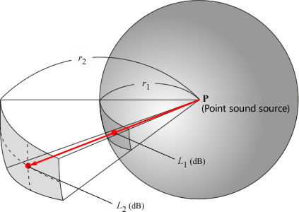
As described in Chapter 1, sound (sound wave) travels through the air at about 340 m/s. Sound loses its intensity (sound pressure level) as it travels farther even when there is no sound shielding or absorbing materials around. In other words, sound is attenuated as it disperses in all directions. This property of sound is called attenuation with distance. Sound is a wave phenomena: as it travels farther from the source, sound spreads over a wider area and hence, the intensity of the sound (sound energy per unit area) weakens. With sound that has a point source, it is propagated in a spherical pattern in free space. It has an area of 4πr2 (where r is the distance from the source of the sound) and the intensity of the sound is attenuated in inverse proportion to the square of the distance. This is called the inverse-square law.


In Figure 10-3, when the sound pressure levels at the distance r1 and the distance r2 from the point sound source P are L2 and L2 respectively, the following equation is true.

(Equation 10-11)

Equation 10-11


For example, doubling the distance reduces the sound pressure level by 6 dB.


Sound dissipation from a point source and attenuation with distance

Figure 10-3: Sound diffusion from a point sound source and attenuation with distance


<< Previous Page    MENU    Next Page >>

© Copyright. ONO SOKKI CO., LTD. All Rights Reserved. | Terms of use | Privacy policy