Non-contact Thickness Meter
CL-5610 series List Controls
Electrostatic capacitance-type
*This product is subject to list controls under Japan’s Foreign Exchange and Foreign Trade Act (FEFTA).

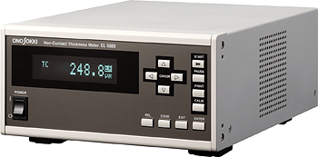
The CL-5610/5610S is used to perform non-contact thickness measurement of objects under measurement including conductors, semiconductors and insulators in combination with the new-developed VE series capacitance type gap detector. The CL-5610/5610S can be connected up to 2 gap detectors and also used as 2-ch displacement meter.
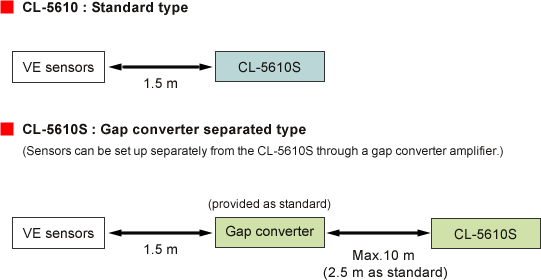
The CL-5610 has a built-in amplifier for a sensor and can be used to connect with the VE sensor directly. This model is effective for off-line measurement on a desktop PC. (The cable length between sensor and a main unit is 1.5 m, cannot be extended.)
The CL-5610S can be used away from the VE sensor through an external amplifier. The cable length between a main unit and an external amplifier is 2.5 m as standard, up to 10-m extension as an option. It is suitable when the main unit of the thickness meter is set up separately from a sensor such as installation to the other equipment.

Features
Wide range of measurement items
Both thickness and gap measurements can be performed. DEVI (deviation value), MAX (maximum value), MIN (minimum value), or Range (MAX-MIN from calculation start time) can be selected for each measurement item.
Performs thickness measurement of conductors, semiconductors and insulators (option) with a single unit
When the CL-0300 optional Insulator Measurement Function is installed, the CL-5610/5610S allows measurement of insulators such as thin plastic film or glass sheet.
*Compound materials cannot be measured.
*Some materials cannot be measured because of their relative
permittivity.
Enables stable thickness measurement of an object with smaller contact area
At measurement of an object on a table coated with fluorine film, the large contact area has been required for stable measurement. The CL-0210 High-impedance Grounding Mode (option) enables measurement of an object with small contact area even if the contact area is smaller than the table. The larger the contact area is, the more the stable measurement can be performed.
The High-resolution Measurement Function (CL-0200 option) enables displaying a minimum resolution at 0.02μm*1.
*1: When the VE-2011/5010/5011 is used. The VE-5010/5011 is available when the measurement range is changed from 20 to 200 by using the optional CL-0201.
Storing of up to 6 calibration informations for sensors.
The CL-5610 series can store up to 6 calibration informations for sensors to select suitable sensor depending on a measurement range and resolution.
Control or data transmission can be performed remotely from PLC* or PC.
Remote, RS-232C, and BCD (option) connectors are provided as external interfaces. Control or data transmission can be performed remotely when the CL-5610 series is incorporated in production facility. Measurement data in BCD format can be obtained from BCD output connector at every 20 ms. Also optional the CL-0110 Outputs Function enables output of measurement value with analog voltage.
* PLC: Programmable Logic Controller
Online monitoring of abnormal value can be performed by the Comparator Function. (When the CL-0100 Outputs Function is installed.)
Measurable objects |
Conductors or semiconductors |
Insulators |
|---|---|---|
Silicon wafer, steel plate, copper-foil substrate, hard disc, aluminum stainless steel, electronic printed wiring board, flexible material, mirrored material, easily damaged material, and any other materials required to be clean including metal plate. |
Glass, polyethylene, polypropylene and other plastic (Thin objects composed of a uniform and simple material throughout can be measured.) |
Please contact your nearest distributor or send an e-mail to us (overseas@ONO SOKKI.co.jp) about measurement of intermediate material, compound material or other materials.
Measurement method
When measuring conductors or semiconductors |
When
measuring insulators |
|---|---|
|
|
Measurement examples
Overview Specificationss
| Measurable objects | Conductors, semiconductors, insulators*1 | ||||||||||||||||||||||||||||||||||
|---|---|---|---|---|---|---|---|---|---|---|---|---|---|---|---|---|---|---|---|---|---|---|---|---|---|---|---|---|---|---|---|---|---|---|---|
| Sensor input | 2-channel (A, B) capacitance type gap detector | ||||||||||||||||||||||||||||||||||
Measurement parameters |
|
||||||||||||||||||||||||||||||||||
| Display mode |
|
||||||||||||||||||||||||||||||||||
Applicable sensor / display resolution |
The display resolution when used in combination with the new VE Series Electrostatic Capacitance type Gap Detectors is as follows.
|
||||||||||||||||||||||||||||||||||
| Accuracy | ±0.15 % FS(standard) ±0.12 % FS(When the optional CL-0200 High-resolution Measurement Function is installed. <not including the VE-8020/8021>) |
||||||||||||||||||||||||||||||||||
| Guaranteed accuracy temperature range | +23 to ±2 °C | ||||||||||||||||||||||||||||||||||
| Display | Fluorescent display tube Display of measurement results can be selected from 1 kind (SINGLE, 1-line) or 2 kinds (DUAL, 2-line). |
||||||||||||||||||||||||||||||||||
| Parameter setting | Parameter required for measurement/calculation can be set up in an internal memory by the each key on a panel. These setup values are stored and recalled at the time of restart. |
||||||||||||||||||||||||||||||||||
| Sampling time | 20 ms |
||||||||||||||||||||||||||||||||||
| Averaging | Moving average:1 to 64 times | ||||||||||||||||||||||||||||||||||
| Interface | RS-232C:Remote control of a main unit and transmission of measurement data. The measurement data can be printed to the DPU-414 printer (sold separately) | ||||||||||||||||||||||||||||||||||
| BCD output function (option:CL-0120) | Outputs any measurement result in BCD
format with 6-digit parallel. |
||||||||||||||||||||||||||||||||||
| Remote function | Remote operation of stop/start calculation, thickness calibration from external.
*Applicable connector: R03-PB8M (TAJIMI ELECTRONICS CO., LTD) |
||||||||||||||||||||||||||||||||||
| SYNC function | The multiple CL-5610/5610S units can be performed with synchronized operation |
||||||||||||||||||||||||||||||||||
Power requirement |
100 to 240 VAC 50/60 Hz |
||||||||||||||||||||||||||||||||||
Operating environment (main unit only) |
Temperature:+23 to ±2 °C (with a guaranteed accuracy
range), 0 to+40°C (operating range)
Humidity:20 to 80 %R.H.(with no condensation) |
||||||||||||||||||||||||||||||||||
Outer Dimensions |
210(W)×99(H)×276(D)mm (CL-5610/5610S main unit) |
||||||||||||||||||||||||||||||||||
Weight |
Approx. 4.5 kg (CL-5610/5610S main unit) |
||||||||||||||||||||||||||||||||||
Option
CL-0110 Outputs Function (Analog output, comparator output)
| Analog output | The number of
terminals:3 (SENSOR A, SENSOR B, A-OUT)
●SENSOR A, SENSOR B ●A-OUT |
||
|---|---|---|---|
| Comparator Function |
The number of outputs:3 (COMP1,
COMP2, COMP3)
●ALL mode: Using comparator 1/2/3 for judgment of UPPER/OK/LOWER. |
CL-0120 BCD Output Function
| Output method | 6-digit parallel, BCD, open collector output |
|---|---|
| Output items | Selectable from THICK, GAP-A, GAP-B. A-B, or DISP 2 |
| Data update time | 20 ms |
| Applicable cable | AA-8207 (3 m, top end open) |
CL-0200 High-resolution Measurement Function
| The CL-0200 High-resolution Measurement Function improves the resolution and linearity of the VE series. |
CL-0210 High-impedance Grounding Mode
| Measurement can be performed stably under the condition with great grounding resistance. |
CL-0300 Insulator Measurement Function
| When the CL-0300 optional Insulator Measurement Function is installed, the CL-5610/5610S allows measurement of insulators. |
CL-015 Wafer slide table (made to order)
|
The CL-015 is a manual slide table that can be used
together with the CL-5610/5610S and VE-1520 Gap
Detectors to perform non-contact thickness measurement
of semiconductors or conductors such as silicon wafers.
Grooves have been provided in the table surface to
facilitate the use of vacuum adsorption tweezers.
Compatible wafer size: Diameter 100 to 150 mm Note: Other special tables for 200-mm and 300-mm wafers can also be made to order. |
VE series Electrostatic Capacitance type Gap Detector
Standard type
| Model name | VE-5010 | VE-1020 | VE-1520 | VE-3020 | VE-8020 |
|---|---|---|---|---|---|
| Measurement range(μm) | 50 to 500 | 100 to 1000 | 150 to 1500 | 300 to 3000 | 800 to 8000 |
| Measurement diameter (mm)*1 | φ6 | φ8 | φ10 | φ20 | φ40 |
| Cable length | 1.5 m (attached cable provided as standard) | VL-1520/1521 cable(1.5m)(sold separately) | |||
| Temperature function | k1=1.7×10⁻⁵, k2=3.4×10⁻⁵ | ||||
| Operating temperature range *2 | 0 to +80 °C | ||||
φ10mm Clamp shape type
| Model name | VE-2011 | VE-5011 | VE-1021 | VE-3021 (Discontinued) |
VE-8021 |
|---|---|---|---|---|---|
| Measurement range(μm) | 20 to 200 | 50 to 500 | 100 to 1000 | 300 to 3000 | 800 to 8000 |
| Measurement diameter(mm)*1 | φ3 | φ6 | φ8 | φ20 | φ40 |
| Cable length | VL-1520/1521 cable (1.5m), (sold separately) | ||||
| Temperature function | k1=1.7×10⁻⁵, k2=3.4×10⁻⁵ | ||||
| Operating temperature range *2 | 0 to +80 °C | ||||
*1 The surface measurement area of the
object under measurement must be larger than the
external diameter of the sensor.
*2 The operating temperature range is the temperature
range in which the sensor can operate, not the operating
range for which accuracy is guaranteed. The operating
range for which accuracy is guaranteed is at 23 ±2 °C.
CL-0201 Measurement Range Change option for the VE-5010/5011
| The measurement range of the VE-5010/5011 can be changed from 20 to 200 μm by using the optional CL-0201. |
Signal cables (sold separately)
| VL-1520 (straight --- straight) | |
|---|---|
| VL-1521 (right-angle --- straight ) |
Revised:2010/12/01
