
![]()
![]()
![]()
Portable 2-channel FFT Analyzer
CF-7200A
| Portable Size | Multi-interface | Direct Operation |
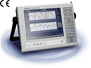
An Advanced FFT Analyzer Covering Sophisticated Needs on Site
Before watching this movie, please make sure Adobe Flash Player in your browser. If this application is not there, visit Adobe download center and get FLASH PLAYER download, please.
![]()
Before watching this movie, please make sure Adobe Flash Player in your browser. If this application is not there, visit Adobe download center and get FLASH PLAYER download, please.
![]()
State-of-the-art Technologies and High Specifications, All in a Compact Body
| ■ Frequency range | 10 mHz to 100 kHz |
| ■ Voltage input range | 10 mVr to 31.62 Vr |
| ■ Data recording | 100 kHz range max., 2 channels |
| ■ Number of analysis points | 6400 points max. |
Multiple Analysis Functions and Application Functions
Analysis Functions
| ■ Time-axis waveform | ■ Power spectrum |
| ■ Frequency response function | ■ Coherence Function |
| ■ Hilbert transform | ■ Inverse Fast Fourier Transform |
| ■ Cepstrum | ■ Tracking analysis (option) |
Calculation Functions
| ■ EU function | ■ Average Summation UNDO Function |
| ■ Differential and Integral Functions | ■ Waveform calculation |
| ■ Zooming Analysis | ■ Frequency Weighting Filters |
| ■ Multi-screen | and more... |
Flexible Data Sharing
Accepts USB, Compact Flash Card, and other general-purpose interfaces for compatibility with PCs and easy data sharing in the existing environment.
Intuitive Button and Touch-panel Operations
The CF-7200A needs no mouse - simply press buttons for all operations. The clickfeel buttons and touch panel allow immediate operations ranging from start/stop of analysis to display of basic functions.
Lightweight, Compact and Highly Portable for All Sites
No setup needed before measurement or troublesome installation on site, such as connecting a personal computer, cables, and power supply to a measuring instrument. All functions necessary for measuring and analyzing noise and vibration are built into the CF- 7200's small file size, for greater flexibility on all sites.
Thanks to the 10.4- inch TFT liquid crystal display, detailed data can be displayed even though QUAD display mode is selected. Simple and easy operation is also possible by touch panel.
With the supplied stylus pen, comments, marks and memos can be entered directly, making it easier to recognize the working efficiency and data. Memos can be saved simultaneously and be shown or hidden.
Selection of main data of the FFT analyzer, selection of the input voltage range and frequency range, and saving and loading of data can be performed directly from the hardware keys on the front panel. The CF-7200A offers simple, quick operations and much more. Even when observing a signal with unknown magnitude and frequency, an appropriate range and display conditions can be set with intuitive continuous button operations. And the signal output function can be turned on or off with the hardware keys, so signal output (option) can be started or stopped with a simple ON/OFF, preventing careless operations.
Each channel is equipped with a CCLD
(power supply for sensors) which can directly drive an
accelerometer, a microphone, and other sensors requiring a
power supply. ![]() TEDS
reads data retained in a TEDS sensor and then automatically
supplies the power to the sensor and performs unit
calibration.
TEDS
reads data retained in a TEDS sensor and then automatically
supplies the power to the sensor and performs unit
calibration.
Can be operated under the condition of noise/vibration-free up to about 5 minutes by means of cooling fan off. Since the CF-7200A itself would not be the source of noise/vibration, analyzing or collecting for subtle noise/vibration is easy without worrying about self-noise/vibration.
Automatically detects cable disconnection of an accelerometer and a microphone*, preventing trouble before measurement.
* Intended for sensors with a built-in constantcurrent type preamplifier.
Equipped with dedicated connectors which directly drive a rotation detectors (Applicable to the MP-981/LG-916) and can be used as an external sampling clock. This makes it easy to perform order ratio analysis (CF-0722 tracking analysis option) which analyzes vibration and noise of engines, motors, and other rotating machinery with rotation-based values.
When the remote controller (DS-0295 option) is connected to the CF-7200A, three main operations can be performed in addition to analysis start/stop. Operating the CF- 7200 from near the working or supervising position makes measurement much easier.
A signal coming from an acoustic or vibration sensor connected to each channel can directly be monitored as sound using a headphone or an external speaker. It makes possible to check aurally whether an intended vibration or sound is input correctly as well as by waveform observation, allowing you to check sensor setup and operation intuitively and with your senses.

| CF card capacity (bytes) | 512 M | 1 G | 2 G | 4 G | 8 G |
|---|---|---|---|---|---|
| Recording time (approx.) | 8 minutes | 16 minutes | 33 minutes* | 33 minutes x 2* | 33 minutes x 4* |
Recording form at: ORF (ONO SOKKI
Record Format)
2-channel, 100kHz-range, data only
The DAT format (binary), TXT format and BMP format can also be saved simultaneously. Data can also be processed using office software and pasted into reports. Since the underlying data in DAT format are securely saved, data can be displayed and processed using PCbased FFT software (DS-2000/3000 Series, XN-8000 Series, or OC-1300 series) and the CF unit.
*Maximum record time at single time
| DS-2000/3000 series Multi-Channel Data Station |
|
| XN-8100 series Report Creation software |
|
| OC-1300 Graph Creation Tool |
|
| Spreadsheet Software |
The USB mass-storage function makes it possible to transfer data of the CF-7200A to a PC through a USB cable* without having to remove a storage medium and without needing special software (Windows ® 2000/XP).
A raw signal coming from an acoustic or vibration sensor connected to each channel can directly be monitored as sound using a headphone or an external speaker. This makes it possible to check aurally whether an intended vibration or sound is input correctly as well as by waveform observation, allowing you to check sensor setup and operation intuitively and with your senses.
Equipped with a built-in microphone for voice recording and a speaker, voice memos can be attached to data and played back when the data is displayed, supporting data arrangements.
New Possibilities for Measurement and Analysis, from Laboratories to Production Sites
Time-axis Waveform
Performs A/D conversion of the raw waveform of an electrical signal of vibration, noise, pressure, strain, etc. coming from a sensor and then displays the result as time-domain data. The Xand Y-axis values at any point can directly be read using the search cursor. The delta cursor function makes it easier to read the time difference and level difference.
Power Spectrum
The power spectrum indicates the magnitude of frequency components contained in a sampled time-axis waveform. Frequency analysis enables detection of abnormal conditions of a facility, which are difficult to estimate through measurement of vibration and noise level and observation of raw timeaxis waveform. The natural frequency of a structure can also be measured.
Frequency Response Function
The frequency response function indicates the ratio of output to input and the frequency characteristics of phase difference. The resonant frequency and phase of a structure can easily be obtained accurately by entering the signal of vibration force generated to Ch1 by an impulse hammer or shaker and then inputting the response (signal of acceleration, velocity and displacement) to Ch2.
Coherence Function
The coherence function is for evaluating the linearity and correlation of input and output of a transmission system, obtained in the frequency domain. The rate of contribution of the input signal to the output signal is represented as a digit from 0 to 1 for each frequency, for evaluating the reliability of the frequency response function, locating a key factor from multiple noise and vibration sources, and evaluating the correlation.
Inverse Fast Fourier Transform (IFFT)
After frequency analysis, a time-axis waveform of a selected band can be obtained again by performing Inverse Fast Fourier Transform (IFFT) for the selected frequency band. For example, by selecting a waveform portion excluding an unnecessary frequency band confirmed in the FFT result and then performing Inverse Fast Fourier Transform (IFFT) for it, a time-axis waveform can be obtained with the selected high frequency band eliminated.
Hilbert Transform
A logarithmic damping factor can be obtained by obtaining a time envelope of a time-axis signal by means of Hilbert transform.
Cepstrum
Cepstrum is obtained by performing Fourier transform of the power spectrum again, allowing detection of the periodicity contained in the spectrum. In addition, reflected waveforms can be eliminated and fundamental frequency extracted by estimating a spectrum envelope from the Cepstrum. Cepstrum can be applied to make an analysis of the sound waves, seismic waves, biowaves, etc.
Tracking analysis (option:CF-0722)
![]()
Tracking analysis is effective for analyzing the noise and vibration in synchronization with rotational speed. This function enables analysis which rotational speeds increase noise and vibration, which rotating parts cause this noise and vibration, and how many times of the frequency component of noise and vibration to the rotational speed occur.
■Constant
ratio tracking
■Constant width tracking
■Time tracking
Rotational tracking analysis (option:CF-0722)
![]()
Equipments with built-in rotating machines, such as engines and motors in products like automobiles and office equipments, may have serious problem when the resonance between rotational equipment of rotating machine and each components will occur. This rotational tracking analysis helps greatly in cases like this.
Multiple Applications with a Single CF-7200A
EU Function
The CF-7200A FFT analyzer can not only directly read values as a voltage (V) but also as a physical quantity. When the input sensitivity has been set and calibration with a reference signal performed for each sensor, waveform values are converted to physical quantities when displayed, eliminating the need to convert from voltage values to physical quantities.
Average Summation UNDO Function
This function is used during average summation to UNDO one average summation. For example, if you end up with a bad result of summation in impulse hammer shaking, you can cancel the result data (by UNDOing the summation) and then try the summation again.
Differential and Integral Functions
First and second order differential operations and single and double integral operations are possible for time-axis and frequency-axis waveforms. Acceleration data from an acceleration sensor can be converted to velocity and displacement; and velocity data from a laser Doppler vibration meter can be converted to acceleration and displacement and displayed. When the EU function is used together, unit conversion (among "m/s2", "m/s" and "m") is also performed automatically.
List Display
This function displays a list of X-axis and Y-axis values for selected points on a displayed waveform. Numeric list for 40 points selected, peak value list and harmonic list enable numeric values to be simultaneously checked for multiple points.
*CF-0771 Signal Output module (option) for 1ch is required.
Input Section
Number of input channels |
2 channels |
||||||||||||||||
|---|---|---|---|---|---|---|---|---|---|---|---|---|---|---|---|---|---|
| Input configuration | Isolated single-ended |
||||||||||||||||
Input connector |
BNC (C02 type) |
||||||||||||||||
| Power supply for sensor (CCLD) |
Supplies the current to a constant-current type sensor via a coaxial cable from the input connector (BNC terminal): +24V/4mA | ||||||||||||||||
| IEEE1451.4(TEDS) (* Note) | Accepts an IEEE1451.4 (TEDS)-based sensor | ||||||||||||||||
Input impedance |
1MΩ ± 0.5% 100pF or less | ||||||||||||||||
Input coupling |
AC: -3dB at 0.5Hz or
less
|
||||||||||||||||
Absolute maximum |
100 VrmsAC for 1 minute (50 Hz) |
||||||||||||||||
Amplitude voltage range |
|
||||||||||||||||
Input range step |
10 dB |
||||||||||||||||
| Input level monitor | OVER: Red LED ON (95 % F.S. or more) FINE: Appropriate level: Green LED ON (-12dB F.S. or more) |
||||||||||||||||
| Auto range | Whenever the 1-frame data is sampled, the amplitude voltage range changes automatically if input range-over occurs. | ||||||||||||||||
| A/D converter | 16 bits | ||||||||||||||||
| Dynamic range | 90 dB or higher: +30 to -30 dBVr
range
|
||||||||||||||||
| Harmonic distortion | -80 dB or less | ||||||||||||||||
| Aliasing | -80 dB or less | ||||||||||||||||
| Amplitude flatness | 20 kHz or less ±0.1 dB 20kHz to 100kHz ±0.2dB (0dBVr or less) |
||||||||||||||||
| Full-scale accuracy | ±0.1 dB at 1kHz | ||||||||||||||||
| Amplitude linearity | ±0.015 % at full scale | ||||||||||||||||
| Cross-talk | -100 dB or less | ||||||||||||||||
| Channel to channel gain accuracy | 20 kHz or less: ±0.1 dB (0 dBVr or less)
|
||||||||||||||||
| Channel to channel phase accuracy | 20 kHz or less: ±0.5 deg (0 dBVr or less)
|
||||||||||||||||
| DC offset | -60 dB F.S.; Auto zero ON, +30 to -20 dBVr range (DC coupling) -40dB F.S.; Auto zero ON, -30 to -40 dBVr range (DC coupling) AUTO ZERO; Collective operation of all channels |
||||||||||||||||
| Trigger | "TRIG ON" LED goes ON when trigger function turns ON LED (TRIG'D) blinks when triggered Position: ±8191
|
||||||||||||||||
| Filter |
|
||||||||||||||||
| External sampling input | ●BNC (C02 type) input: EXT SAMP Connector
●R03-R6F input: REV SENSOR Connector
|
||||||||||||||||
| Remote control | When the DS-0295 Remote Controller is connected, start/stop and custom-selection operations are possible. | ||||||||||||||||
| Voice input/output for voice memo | Sound input and playback with a built-in
microphone and speaker External MIC input: φ2.5 stereo mini
jack input (L) |
* Note: If a TEDS supported sensor made by other companies is used, TEDS information may not be read depending on the type of a TEDS tip included in a sensor.
1. If you are considering the purchase of a TEDS sensor made by other companies, please consult to the manufacturer or dealer of the TEDS sensor, and perform the operation check.
2. When you want to use a TEDS sensor you already have with the TEDS supported measurement instruments made by Ono Sokki, please perform the operation check with a demonstration product of Ono Sokki. (Please consult your nearest distributor or Ono Sokki sales office nearby.)
Display Functions
| Display mode | SINGLE screen display mode/DUAL screen display mode/ TRIPLE screen display mode/QUAD screen display mode/OVERLAY display mode |
|---|---|
| 3D (color) Display | ●X axis Sampling: 16384 (MAX), the number of lines: 6400 (MAX) ●Z axis 10/20/30/50/100/200/400, Z axis angle: 45/60/75/90 ●Y axis 50/100/150/200 ●Display mode 3D (color) / 3D (color) & data / 3D (color) & data & trace |
| List display mode | Harmonic /Total Harmonic Distortion Peak list display/Optional point list/Octave list display/TEXT format |
| Label function | Input: Direct handwriting using a stylus pen Color: 8 colors Line type: 3 different thicknesses Display: Show/hide |
| Search function | Delta function X mode/Y mode/XY mode Partial OA/Peak/p-p/MAX-MIN/Search enhance |
| Vertical axis unit | rms/PEAK/0-p/p-p/V/V2/PSD/ESD Automatic unit conversion function Unit conversion by integral/differential operations (displacement ←→ velocity ←→ acceleration) |
| Vertical axis scale | Auto/Manual/Default/Gain/Phase unwrap function/Delay |
| Horizontal axis unit | Hz/ r/min /Order /s(sec)/EXT |
| Horizontal axis scale | Zooming with default/delta cursor |
| Calculation function | Four arithmetic operations among waveforms/Differential and integral operations/FRF equalization/Inverse Fast Fourier Transform/ Hilbert transform/Damping calculation by half-value width method |
Display Unit
| Size | 10.4-inch |
|---|---|
| Type | TFT color LCD with touch panel function |
| Resolution | 800 x 600 dots |
| Lighting (back light) | Cold-cathode tube, 2-level brightness adjustment (Back light power saving timer: 1 minute to 60 minutes) |
Analysis Section
| Frequency accuracy | ±0.005 % of reading (±50 ppm) | ||||||||||||||||
|---|---|---|---|---|---|---|---|---|---|---|---|---|---|---|---|---|---|
| Frequency range | 10 mHz to 100 kHz | ||||||||||||||||
| Sampling frequency | Frequency range x 2.56 (internal sampling) | ||||||||||||||||
| Number of sampling points/analysis points |
|
||||||||||||||||
| Overlap processing | MAX/66.7%/50%/0%/Optional setup | ||||||||||||||||
| Window functions | Rectangular/Hanning/Flat-top/Force/Exponential/User-defined | ||||||||||||||||
| Delay function | Time frame of channel 2 can be delayed by 0 to 8191 points with reference to channel 1. | ||||||||||||||||
| Time-axis waveform processing function | The time-axis waveform processing function can be selected with
soft keys. First and second order differentials/Single and double integrals Absolute value conversion/DC cancel/Trend elimination /Smoothing /Hilbert conversion |
||||||||||||||||
| Real-time analysis | 40kHz/2 channels (internal sampling: 4096 points) | ||||||||||||||||
| Search enhance | Calculation resolution: x32 Y-axis accuracy: ±0.1dB |
||||||||||||||||
| Averaging mode | Setting of number of averages: 1 to 65535 Averaging setup time: 0.1 to 999 seconds (in 0.1-second steps) Averaging can be stopped in terms of the number of times or time.
A/D-over cancel/Double hammer cancel/Averaging permission select function (ADD+1)/Averaging undo function |
||||||||||||||||
FFT operation |
32-bit floating point (IEEE single-precision format) |
Processing Functions
| Time domain | Time-axis waveform/Auto-correlation function/Cross-correlation function/Impulse response/Cepstrum/Liftered envelope/Hilbert transform | ||||||
|---|---|---|---|---|---|---|---|
| Amplitude domain | Amplitude probability density function/Amplitude probability distribution function | ||||||
| Frequency domain |
|
Memory Functions
| Data record |
|
||||||||||||||||||
|---|---|---|---|---|---|---|---|---|---|---|---|---|---|---|---|---|---|---|---|
| Data file | Max. recordable memory capacity: 300 data items or less in internal memory/ CF card (depending on the CF card capacity) | ||||||||||||||||||
| File format | Analysis data can be saved simultaneously with three different formats: DAT, TXT and BMP (TXT and BMP selectable). | ||||||||||||||||||
| Panel condition memory | 50 types | ||||||||||||||||||
| Contents of panel condition memory | Memorizes parameters which can reproduce all software and hardware settings in the panel condition memory mode. | ||||||||||||||||||
| Voice memo memory | 300 data items or less (depending on the CF card capacity) | ||||||||||||||||||
| Handwritten memo memory | 300 data items or less (depending on the CF card capacity) | ||||||||||||||||||
| Recording device | Main unit built-in memory (fixed) or CF card can be selected.
|
Output Functions
| USB Interface |
|
||||||||||||
|---|---|---|---|---|---|---|---|---|---|---|---|---|---|
| External SPEAKER output |
|
||||||||||||
| Printer output | Printer interface: USB Device: Accepts thermal printers of recommended model Source: On-line data, Saved data |
||||||||||||
| Monitor output | Number of connectors: 2 (Each connector outputs Ch1 or Ch2 data) Output voltage: 1Vrms F.S. ±1% for input voltage range F.S. (1kHz sine wave, 1MΩ load) Impedance: Approx. 33Ω Source: Input signal (after analog filtering) Connector: φ=2.5 monaural jack |
Signal Output (CF-0771) ― Option
| Number of channels | 1 | ||||
|---|---|---|---|---|---|
| Output connector | BNC (C02 type) | ||||
| D/A converter | 16 bits | ||||
| Maximum output voltage | ±10V (Amplitude + DC offset) | ||||
| Amplitude resolution | Approx. 2.5mV | ||||
| Offset resolution | Approx. 5mV | ||||
| Output format | Unbalanced output | ||||
| Protection circuit | Short-circuit protection | ||||
| Isolation | No isolation (No isolation between chassis and digital common) | ||||
| Output impedance | 0Ω: Low
impedance output (unbalanced) 50Ω: ±10% |
||||
| Output current | 50mA (If 10mA is exceeded, harmonic distortion, flatness, and crest factor are not prescribed.) | ||||
| Output mode | ●Continuous
●Burst
●Sine Sweep
|
||||
| Taper function | The output can be gradually increased or decreased when the
signal is turned ON or OFF.
|
||||
| Frequency range | 0.1mHz to 100kHz (sine wave) , Band limiting not possible | ||||
| Harmonic distortion | -70dB or less (Prescribed with 1V0-p amplitude value) | ||||
| Output ON/OFF | ●Turned ON or
OFF with the SIGNAL OUT button (Turned OFF at the time of
activation)
●ON/OFF for each button
|
||||
| Output waveform | Sine wave, Swept sine, Pseudo random, Random, Impulse | ||||
| Analysis frame length | 256 to 4096 | ||||
| Zoom mode analysis | Possible for all waveforms | ||||
| Spectrum flatness | ±1.0dB or
less: 20kHz to 100kHz ±0.2dB or less: 0 to 20kHz |
||||
| Crest factor | Sine wave:
Approx. 1.41 Swept sine: Approx. 1.4 to 1.6 Pseudo random: 3.3 or less Random: 3.3 or less Impulse: 32.0 or less |
||||
| Pink filter | Analog filter: -3dB/oct ±1.0dB (prescribed for 20Hz to 20kHz) |
Miscellaneous Functions
| Condition view | List display of condition settings Can be saved in the XML (Text) format of condition. |
||||||||||
|---|---|---|---|---|---|---|---|---|---|---|---|
| Remote controller (option) | ●Operating switches: 5
(START/STOP/F1/F2/F3)
|
||||||||||
| Clock | Date (year, month, day) and time (hour, minute, second) | ||||||||||
| Operation beep | Can be turned ON or OFF (in conjunction with ON/OFF of warning beep) | ||||||||||
| Warning beep | Can be turned ON or OFF (in conjunction with ON/OFF of operation beep) |
General Specifications
Power requirement |
Input voltage: 10.5 to 16.5VDC |
|---|---|
| Power connector | DC jack (EIAJ
TYPE5) Outer side: Negative electrode, Inner side: Positive electrode |
| Power consumption | Approx. 70 VA (AC adapter used) |
| Operating temperature range | 0 to +40°C |
| Storage temperature range | -10 to +50°C (including an external secondary battery) |
| Functional grounding terminal | Grounding terminal for noise elimination |
| Outside
dimensions (not including the handle and protrusions) |
328mm(W) x 246mm(D) x 78mm(H) (battery not mounted)/328mm(W) x 246mm(D) x 120mm(H) (battery mounted)/Refer to outer dimensions for details |
| Suspension of chassis | VESA standard 100 x 100 (mm)/Can be suspended by attaching a φ5 adapter |
| Stylus pen | Can be stored in the main unit (accessory) |
| Carrying handle position | 0° (top level position)/30°/60°/90°/110°/130°/180° (bottom level position) |
Main unit cooling |
Forced-air cooling by an electric fan Operating noise: 32.5dB(A) (Reference value) |
| Weigh | Approx. 3.4 kg / Approx. 5.0 kg (battery pack mounted) |
| Standard Accessories | ・CF-0792 Battery Pack ・CF-0701 Panel Protection Cover ・CF-0702 Stylus Pen ・CF-0703 USB Connection Cable ・PS-P20018A AC Adapter ・CF card (512 MB) ・USB memory (for update) |
AC Adapter (PS-P20018A)
| Input voltage | 100 to 240VAC |
|---|---|
| Input frequency | 50/60Hz |
| Output voltage | Rating 15V |
| Safety standard | Electrical Safety Law/CE/ÜL |
Battery Pack (CF-0792)
| Battery | Lithium ion secondary battery |
|---|---|
| Shape | Fixed to the rear section of the main unit (detachable) |
| Operating time | Operates for 4 hours under standard operating conditions (2ch FFT analysis/Signal output option not mounted/25°C room temperature with a new battery) |
| Remaining battery level display | Displays the remaining battery level when operating on the secondary battery 4-level display. |
| Minimum remaining battery level | Displays a warning message and shuts down automatically. |
| Charge | Charged by the AC adapter when the main unit power is OFF. |
| Charge time | Approx. 8 hours (power OFF) |
Options
| Model Name | Product Name |
|---|---|
| CF-0722 | Tracking Analysis Function (Order Ratio Analysis Function) |
| CF-0771 | 1ch Signal Output Module |
| CF-0792 | Battery Pack |
| CF-0701 | Panel Protection Cover |
| CF-0702 | Stylus Pen |
| CF-0703 | USB Connection Cable |
| CC-0025 | Soft Carrying Case |
| CC-0071A | Hard Carrying Case |
| DS-0295 | Remote Controller |
| PS-P20018A | AC Adapter |
| Rack Mount Adapter (made to order) |
Recommended Products
| Model Name | Product Name | Manufacturer |
|---|---|---|
| HM-186 | Speaker microphone | ICOM INCORPORATED |
| TS512MCF100I | CF card 512 MB | Transcend ® Information, Inc. |
| TS1GCF80 | CF card 1 GB (80 x) | Transcend ® Information, Inc. |
| TS8GCF100I | CF card 8 GB | Transcend ® Information, Inc. |
| TS512MJF110 | USB memory 512 MB | Transcend ® Information, Inc. |
| TS1GJF110 | USB memory 1 GB | Transcend ® Information, Inc. |
| TS2GJFV10 | USB memory 2 GB | Transcend ® Information, Inc. |
| TS2GJFV33 | USB memory 2 GB | Transcend ® Information, Inc. |
| BL-112 series | Thermal printer | Sanei Electric Inc |
Comparison of the specification ; CF-7200 and CF-7200A
| CF-7200 | CF-7200A | ||
|---|---|---|---|
| ■Function | Four arithmetic operations among waveforms | None | Provided |
| The number of panel condition memories | 10 | 50 | |
| The number of data files | 200 | 300 | |
| The number of memories for voice memo | 200 | 300 | |
| The number of memories for handwrite memo | 200 | 300 | |
| AUTO STORE | None | Provided | |
| Y-axis calibration unit (EU) input function | None | Provided | |
| Applicable CF card | 2 GB | 8 GB | |
| Recording time of data record | Approx. 33 minutes | Approx. 33 minutes x 4 | |
| ■General Specification | Power consumption | Approx. 60 VA | Approx. 70 VA* |
| Weight | Approx. 3.2 kg/ 4.8 kg | Approx. 3.4 kg / 5 kg | |
*The operating time of battery is not changed.
Revised:2017/3/31