
![]()
![]()
![]()
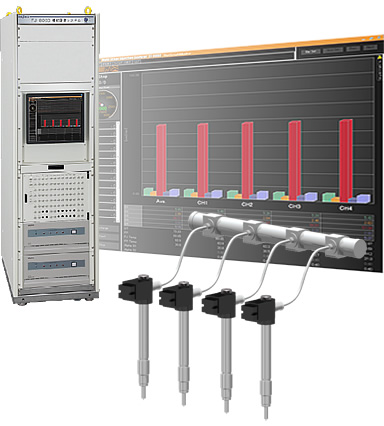
Common rail method already is commonly known as an injection system of diesel engine now. That system enables multi-stage fuel injection by offering high injection pressure in various driving situation. Adopting the common rail system helps improving fuel consumption, reducing noise and vibration, because the system can make the fuel approximate complete combustion which suppresses PM and NOx generation. FJ-8000 series is the multi-stage injection analyzer that supports more accurate injection by measuring injection quantity, injection rate, injection timing, and injection period by multi-stage injection of common rail system in the environment that is near to an actual vehicle environment.
Features
Highly accurate multi-stage injection measurement( ±0.25 % of reading)
*when high precision type usedUp to 15 stages of fuel injection quantity·fuel injection rate measurements at the same time
Data memory of continuous 50,000 cycles
Injection quantity detection section
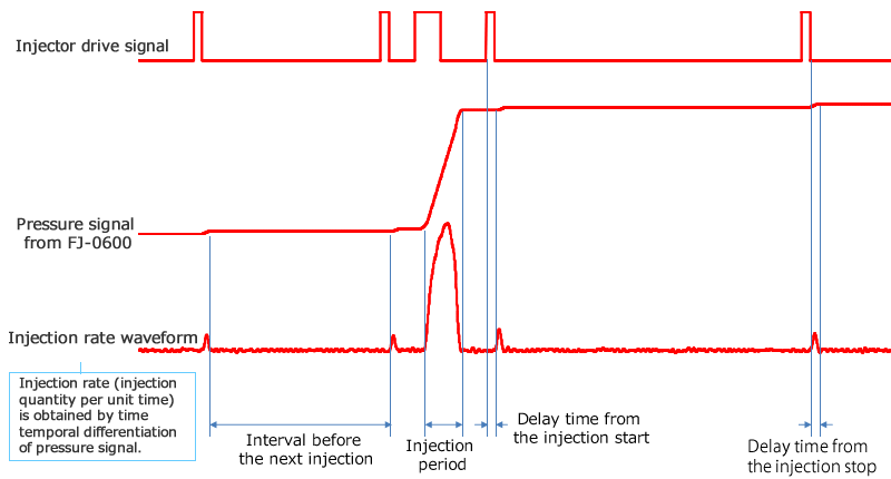
High-precision analysis of fuel injection timing with high-speed sampling
High-speed sampling (injector drive signal 1 MHz, pressure signal 200 kHz) allows analysis of interval before the next injection,and analysis of delaytime of injection start/stop with high accuracy.
Real-time data display
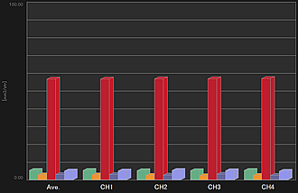
1.Bar graph
Bar graph display of injection quantity for each cylinder, and each injection state
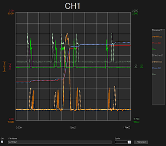
2.Injection rate monitor
Simultaneous display of injection rate, pressure, and external input signal for 1 ch (injection command etc.)
The current data can be overlaid on the saved existing data
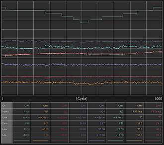
3.Trend graph
Trend display up to 8 kinds, 3000 cycles of data
4.Dual monitor
Simultaneous display of trend graph and bar graph
5.Numerical monitor
Display of numerical data for each cylinder including injection quantity, injection period and detector internal temperature
Data Analysis
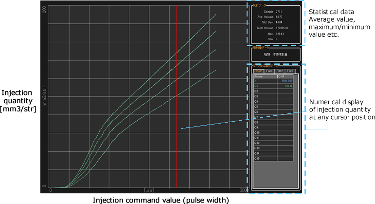
TQ-Q graph( Injection command value-Injection quantity graph)
TQ-Q graph shows changes in fuel injection quantity in response to fuel injection commands. The horizontal axis represents fuel injection commands while the vertical axis represents fuel injection quantity.
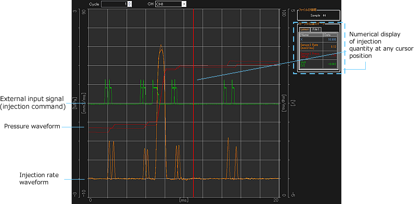
● Injection rate graph
A fuel injection rate graph shows a pressure waveform, a fuel injection rate waveform and waveform for a selected channel for each cylinder.
●T-Q graph ( Horizontal axis:cycle vertical axis:injection quantity)
Displays the variation of injection quantity for each cylinder at one cycle
●N-Q graph ( Horizontal axis:rotation speed Vertical axis:injection quantity)
Displays the change in the injection quantity for each cylinder at pump rotating speed
●Histogram
A histogram shows the distribution of fuel injection quantities for preset stages
●Statistical data
Displays the injection quantity, injection period, average of detector internal temperature, standard deviation, and maximum/minimum value
●Data list
Data is listed in graph format of injection quantity in one cycle, injection period, and detector internal temperature.
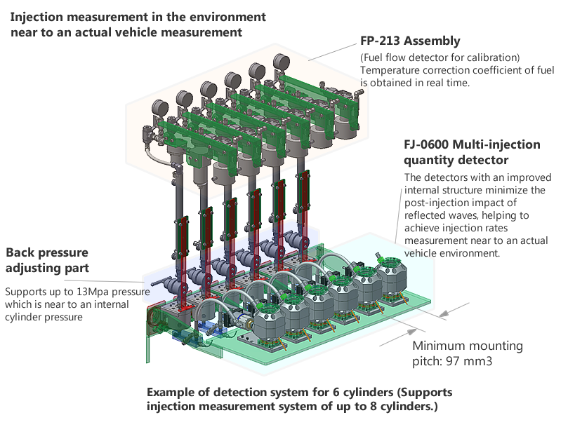
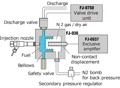
System Configuration
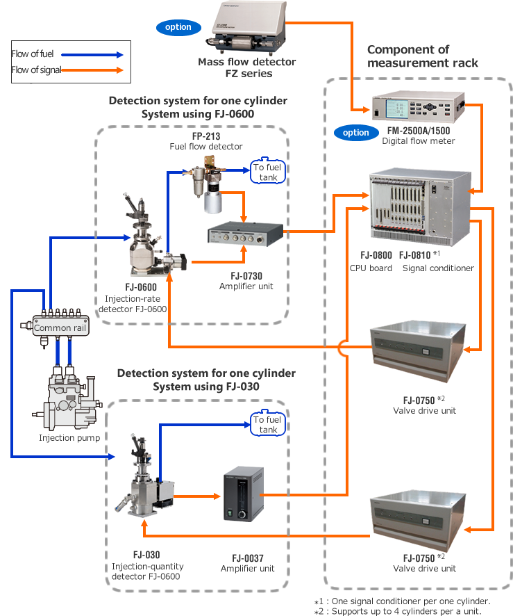
Measurement principle
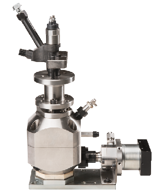
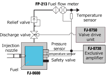
FJ-0600 Injection-rate detector
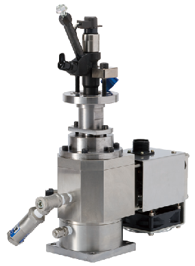
FJ-030 Injection-quantity detector
This is the method to calculate the injection quantity before and after the injection by the bellows position. The injected fuel is discharged with the solenoid valve after the measurement is completed, for the preparation of the next injection. High pressure gas is added from inside of the bellows, which becomes the back pressure for the nozzle.
Overview specification
| Name | Model name | Item | Specification | |
|---|---|---|---|---|
| System specification | Major fucntion *1 | Measurement of the fuel injection quantity and injection rate of a multi-stage fuel injection system of gasoline and diesel engine | ||
| Number of cylinders *2 | Max. 8 cylinders | |||
Number of injection stages *3 |
Max. 15 stages | |||
| Measurement item *1 | Fuel injection quantity (each stage and total injections), fuel injection rate, number of injections, pump rotation, temperature, and back pressure | |||
| Fuel injection quantity *1 | Instantaneous value, average value, integrated value, standard deviation, max. value, min. value, injection period, injection interval, and cylinder-to-cylinder deviation | |||
| Display item *4 | 1. Real-time measurement display (bar graph and numerical display of each stage injection quantity+ total injection quantity)
2. Histogram of injection quantity 3. Cycle injection quantity graph (T-Q graph) 4. Rotation speed-injection quantity graph (N-Q graph) 5. Injection period (each injection and interval) 6. Measurement data of each number of injecton (1 to 5 stages and total injection quantity, temperature, rotation speed, and back pressure) 7. Injection rate waveform 8. Average value, integrated value, standard deviation, max. value, min. value and cylinder-to-cylinder deviation of each injection quantity |
|||
| Memory capacity | Max. 5000 cycles in 1 cylinder | |||
| Fuel injection detector | Model name | FJ-06XX | FJ-030 | |
| Measurement range *3 | Total injection quantity: 0 to 100, 200, 300 3 /str Support injection quantity: up to 20% of total injection quantity |
|||
| Measurement accuracy | ±0.1% or less of full scale
(Measurement injection quantity: 20% or less of full scale)
±0.5% or less of reading value (Measurement injection quantity: 20% or more of full scale) |
|||
| Resolution | 1/1000 of max. measurement injection quantity | |||
| Injection period | 1 to 50 Hz (60 to 3000 r/min) | |||
| Nozzle back pressure | 1 to 4 Mpa, 1 to 13 Mpa(option) | 1 Mpa (Adjustment is option) | ||
| Back pressure medium | Fuel | N2 gas or dry air (Prepared by customer) | ||
| Fuel temperature | 10 to 120 °C (Inside of the detector) | |||
| Pressure detector | Semiconductor type (for back pressure measurement)
Piezoelectric type (for fuel quantity measurement) |
Semiconductor type (for back pressure measurement) (Option) | ||
| Temperature sensor | Resistance temperature detector (Pt100Ω) | Resistance temperature detector (Pt100Ω) (Option) |
||
| Fuel flow detector for calibration | FP-213*6 | Application/ measurement range | Fuel flow detector for injection quantity calibration/ 0.06 to 60L/h | |
| Measurement accuracy | ±0.5% reading value (when 0.18 to 60L/h), ±0.0009L/h or less (when 0.06 to 0.18L/h) | |||
| Amplifier unit | FJ-0730 | Amplifier for FJ-0600A injection quantity detector: 1 unit is required for 1 detector. (Place it near by the detector) | ||
| FJ-0037 | Amplifier for FJ-030 injection quantity detector: 1 unit is requeired for 1 detector. (Place it near by the detector) | |||
| Signal conditioner | FJ-0810 | Number of unit of connecting detector | 1ch, select either FJ-030 or FJ-06xx | |
| Pressure signal input section | Injection quantity--- for FJ-06xx, back pressure | |||
| Displacement signal input section | Injection quantity--- for FJ-030 | |||
| Temperature signal input section | Injection quantity detector internal temperature, temperature of FP-213 Fuel flow detector | |||
| Flow signal input section | Pulse signal from the FP-213 Fuel flow detector | |||
| Injection rate signal output section | "0 to 5 V/ 0 to FS mm3/ms (When calibrating), FS value are 100 mm3/ms, 200 mm3/ms, 300 mm3/ms,or 400mm3/ms depending on measurement range. Output the support injection quantity and main injection quantity separately. Digital low pass flter is attached (1, 1.2, 1.5, 2, 2.5, 3, 4, 6, 8 kHz and through). | |||
| Angle pulse signal input section | Reference pulse: 1 P/R, Angle pulse: Select from 360, 720, 900, 1800, or 3600 P/R | |||
| CPU | FJ-0800 | Number of unit of signal connector | Max. 8ch | |
| Valve drive unit | FJ-0750 | Number of valve drive | Required when 4ch of signal conditioner (FJ-0810) is used. | |
| Option | FJ-0870 | Injection period/Interval measurement function | Measures/displays the injection period and interval. | |
| FJ-0871 | Injection start/end delay time measurement | Measures the time between rising /falling of the external input pulse (drivng pulse/TTL level positive logic of the normal injector) and injection start time, or injection end time. | ||
| FJ-0872 | Injection rate waveform display/output function | Displays and saves the detected signals of injection/injection rate waveform for every selected cylinder injection. Display/output of sampled data by 200 kHz from a detector. You can perform data processing and analysis up to 100 sampling data. | ||
| FJ-0873 | Trend graph display function | Selected 16ch data including selected cylinder (revolution, injection quantity of each cylinder, back pressure, injection period, temperature, etc.) can be trend display in every cycle. *Display is switched in every 8ch. |
||
| FJ-0874 | Analog input | Input: Max. 16ch, Input singal: 0 to 10V, Sampling the voltage singal form the external measuring instrument in every 1 P/R and convert it to physical value to save it to the data sheet (CSV format). A/D board is required. | ||
| FJ-0875 | Analog output | Selects 16ch from max. 136ch of injection quantity, pump revolution, injection period, injection interval, rising time, falling time, pressure, temperature, etc. (Injection rate is provided as standard). D/A board is required. | ||
| FJ-0876 | Injection judgment function |
Whether fuel has been injected or not is determined based on the following criteria using injector driving signals. |
||
| FJ-0877 | Bulk modulus correction function | Reads the temperature and modulus of volume coefficient data of the detector and corrects the modulus of volume coefficient in temperature to display the accurate injection quantity. | ||
| FJ-0878 | Mass conversion measurement function |
Converts the injection quantity to mass by obtaining the density data. | ||
*1 Detection delay might occur structurally. Please use the result of injection rate measurement (injection period, interval) as a reference..
*2 Measurement for 1 cylinder is also available.
*3 System of 5 stages / 10 stages are also available.
*4 The value is offline display except for real time injection amount display.
*5 The detector of other detection range (100 mm3/str or less, 400 mm3/str or more) can be optionally made. The minimum injection quantity differs according to the detection capacity.
*6 FP-2140H(wide measurement range type: 0 to 120 L/h), FP-213S (low pressure loss type: 0.01 kPa or less) can also be used.
*Microsoft® Windows® are registered trademarks of Microsoft Corporation in the United States and other countries.
*Other product names are trademarks or registered trademarks of each individual company. The copyrights are reserved by each individual company.
Revised:2017/03/31