Ultrasonic vibration measurement of a wire bonder for ball bonding using a laser Doppler vibrometer
A wire bonder is a device that connects a conductance wire between a silicon chip, which is a core of IC or LSI, and a lead frame. Currently, ultrasound waves are generally used for wire bonding and the ultrasonic vibration application condition is focused on as one of the important parameters that determine the quality of bonding. To achieve stable bonding, the vibration amplitude at the tip of the capillary must be stabilized and therefore, the need for direct measurement of the vibrations at the tip of the tool is increasing each year.
This application shows a method for measuring capillary vibration conditions (microscopic displacement) using a laser Doppler vibrometer.
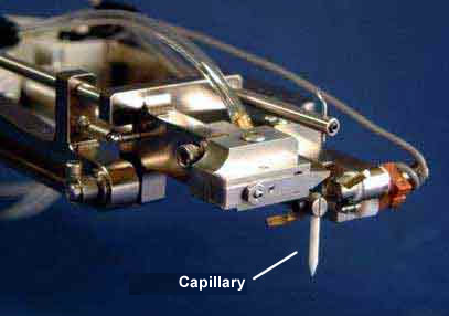
The ultrasonic wave mechanism section that is used for a wire bonder comprises a bolting Langevin type transducer, a metal horn for increasing the vibration amplitude, and a tool, which is a solderless terminal (or capillary). In general, a vibration frequency of around 60 kHz or recently sometimes 100kHz is applied.

The vibration condition of a capillary using the laser Doppler vibrometer (microscopic displacement) cannot be measured under the situation that wire bonder is being carried out bonding operation continuously (auto bonding). Because the laser light cannot follow up the bonding machine during operation. By using "manual bonding·step mode", which function enables a single bonding operation only once, capillary vibration condition at the moment of a bonding operation can be measured.
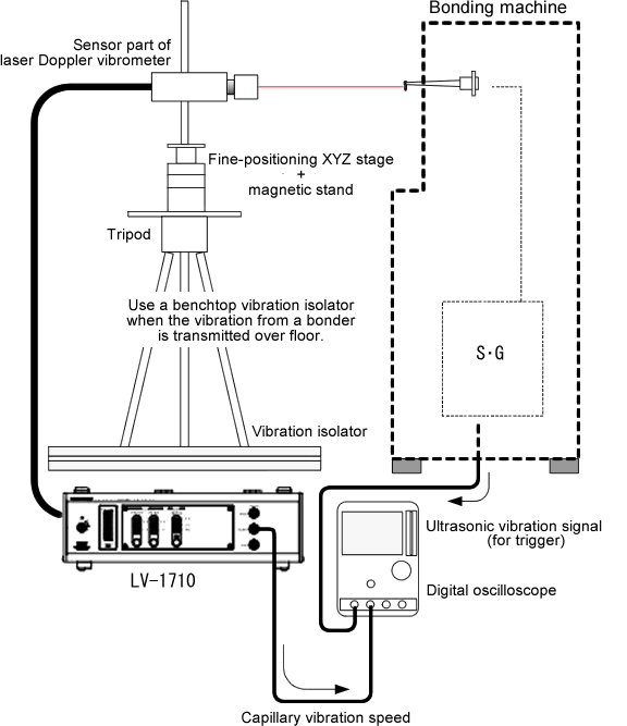
Configuration
| Model name | Product name | |
|---|---|---|
| 1 | LV-1710 | Laser Doppler Vibrometer |
| 2 | LV-0030 | Large-format magnetic stand |
| 3 | LV-0015 | Fine-positioning XY-stage |
| 4 | LV-0016 | Fine-positioning Z-stage |
| 5 | LV-0017A | Large size tripod |
| 6 | LV-0018A | Steel plate (magnetized iron sheet) |
| 7 | LV-0301 | 90-degree reflecting mirror (use at the time of lead frame measurement) |
| 8 | Digital oscilloscope (or an equivalent high-speed storage oscilloscope) |
Example of measurement data
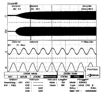
Top:Capillary oscillation velocity waveform
Bottom:Original US (ultrasonic wave) signal
Each waveform of the bottom section:Zoom
waveform of 10μs/div
![]()
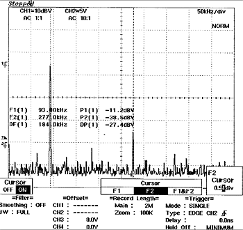
Frequency analysis data by FFT
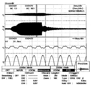
Top:Capillary
oscillation velocity waveform
Bottom:US(ultrasonic wave)signal
Each waveform of the bottom section:Zoom
waveform of 10μs/div
![]()
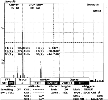
Frequency analysis data by FFT
Measurement point
Since the characteristics vary depending on the type of the IC that is manufactured and the bonder/wire that are used, industry standards cannot be created so that individual handling is applied. Therefore, since some time for creating standards is required, the method will not be effective immediately. As constant monitoring is not possible, some experience is necessary for measurement.
Revised:2012/07/02
