
![]()
![]()
![]()


Use the terminal mode to set the N-0
■ Terminal mode
VT-100 which is dedicated terminal device made by DEC is supported as a standard terminal by many minicomputers and workstations. TS-2600 uses the same escape sequence as the VT-100 terminal to use the full-screen terminal mode.
■ Description of operation keys and their functions
There are two modes in the terminal mode, such as monitor mode and set mode. In monitor mode, the indication values of torque and rotation as well as switch status are displayed for each gate time. In set mode, torque zero correction value and N-0 correction value can be set. The following figure shows the terminal mode screen.
·Monitor mode
| 「ESC」 | Ends terminal mode. |
| 「S」 | Enters to set mode |
| 「Z」 | Performs torque zero correction in the currently set direction of rotation. |
·Set mode
| 「ESC」 | End set mode to return to monitor mode. |
| 「BS」「DEL」「←」 | Deletes one character. |
| 「+」「−」 | Input sign (available only for N-0 correction value setting) |
| 「0 」to「9 」 | Input numeric values. |
| 「ENTER」 | If you make a mistake for moving the setting item or inputting the definitive value of setting value, it is necessary to make items one round by continuously pressing the [ENTER] key. |
| 「!」 | Sorts (relisting in the ascending order of rotation) N-0 correction value and calculates the table to store the results in the backup memory. (Correction is available when the parameter setting is ON.) At the same time, torque zero correction values are written in the backup memory. |
·Key operation common to both modes
| 「CTRL 」+「L」 | Updates the screen (press the [L] key together with the [CTRL] key). |
■ Input method of N-0 correction value
Input the data recorded in "Input of Detector Frequency Characteristic (N-0) Correction Value". (Please refer to the following "Preparation of N-0 correction value"). On the terminal screen, R stands for rotation and T stands for torque value.
1. Press [S] to start set mode.
2. Press [ENTER] to move the cursor to input rotation and torque value.
3. Press [!] to store the value to the backup memory.
4. Input the frequency characteristic (N-0) correction value of the detector.
The torque value may be displayed even the shaft is rotating in no-load condition, depending on the frequency characteristic of the detector.
Because this value is reproducible, high precision measurement becomes possible by setting a correction value for each rotating speed. Set parameter 1 to 4 to OFF.
·Preparation of N-0 correction value
Prepare the following table or recording torque count for each rotating speed.
Rotating speed (r/min) |
0 |
1000 |
2000 |
3000 |
4000 |
5000 |
|---|---|---|---|---|---|---|
Torque count |
2 |
[Note] In torque count field, enter numbers ignoring the decimal position. <Example: 0.02 to 2>
In no-load condition (with nothing on either side of the shaft), rotate the shaft of the detector by the motor to record the indication of torque for each rotating speed. When measurement is to be made in both CW and CCW directions, prepare a table for each direction.
Up to five points of count torque in each CW and CCW direction can be inputted in the TS-2600. Input points can be approximated with a straight line to perform correction of other than input points.
It is possible to make the interval of rotation finely where the data greatly changes, and coarsely where the data does not change so greatly.
Example:Rotation number → 500, 1000, 1500, 2000, 5000
·Inputting the N-0 correction value
To input the N-0 correction value, it is necessary to connect the RS-232C cable.
·N-0 correction value becomes effective when parameter 1-4 in the internal setting section is set to ON.
·The setting of N-0 correction value can be checked by turning ON the TEST switch (parameter setting 2 -3) and setting MEAS/CAL switch to CAL.
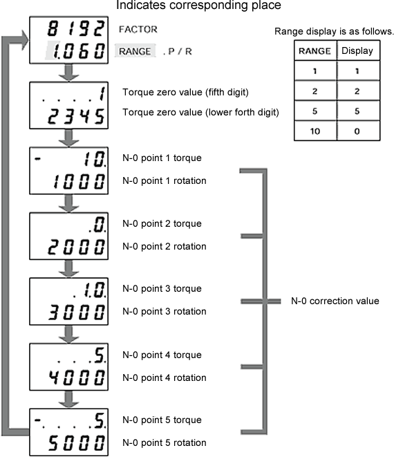
■ Confirmation procedure of the N-0 correction value
Display the FACTOR and N-0 correction value in the torque display and rotation display by the CAL function. (Caution) Setting of parameter is necessary.
1. Turn ON the No.3 DIP switch of 4-bit in the parameter setting 2.
2. Set the MEAS/CAL switch to CAL of the TEST switch (parameter setting 2-3).
3. The torque display and rotation display is changed in order as follows when the TRQ ZERO switch is pressed.
(Torque display: Torque factor, etc. Rotation display: Torque range, etc.)
<Caution for the display>
|
Revised:2002/03/15
