
![]()
![]()
![]()


1. Overview
RS-232C is the standard serial communication interface established by EIA (Electronic Industries Association). The RS-232C interface of TS-2600 enables the reading of data or the writing of N-0 correction values via minicomputer or personal computer, using an appropriate program. When your personal computer supports the functions of terminal emulator or VT-100 terminal emulator, it is possible to write torque zero correction value and N-0 correction value in TERMINAL mode of TS-2600.
2. Specifications
| Standard | Applicable for EIA and JIS X5101 |
|---|---|
| Communication method | Asynchronous full-duplex mode |
| Transmission speed (baud rate) | 9600 bps |
| Character length | 8-bit |
| Parity check | No |
| Stop bits | 1 bit |
| X parameter control | XON - XOFF control |
| Terminator | CR + LF |
3. Connecting a personal computer
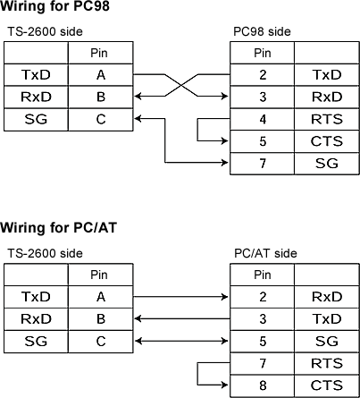
Wiring
When the connected external equipment uses control signal, it is necessary to neglect the control signal by wiring or program.
Wiring example
Applicable connector model name (signal cable side): R03-PB3M (Made by Tajimi electronics co., ltd)
Standard connection (to communicate only via TxD and RxD signal lines)
4. Description of signal
| Signal name | Function | Input/output |
|---|---|---|
| TxD(BA) | Transmit data | Output |
| RxD(BB) | Receive data | Input |
| RTS(CA) | Request for transmission | Output |
| CTS(CB) | Permit transmission | Input |
| SG(AB) | Signal grounding | − |
(1) TxD (Transmit Data)
Transmission data output signal, generally it is in MARK status (-9 V).
+9 V level … 0 (Space)
−9 V level … 1 (Mark)
(2) RxD (Receive Data)
Received data input signal
+9 V level … 0 (Space)
−9 V level … 1 (Mark)
(3) SG (Signal Ground )
Common for signal
5. Function
Write
| Torque zero correction value | CW/CCW One point for each CW/CCW |
|---|---|
| N-0 correction value | CW/CCW Five points for each CW/CCW |
| Auto zero | Zero correction value setting |
Read
| Torque measurement value | A value averaged by the measurement gate time which is set by parameters 1-7 and 1-8. |
|---|---|
| Rotation measurement value | A value averaged by the measurement gate time which is set by parameters 1-7 and 1-8. |
| Setting value | The setting of range, factor, P/R, decimal point, torque zero correction value (CW/CCW), N-0 correction value (CW/CCW), rotation direction and parameter setting. |
| Signal status | Torque signal input, rotation signal input, READY and trigger |
6. Command list
Command terminator is CR (0DH) or LF (0AH), and CR + LF is added to the output from the TS-2600. Xoff (^S : 13H) pauses output and Xon (^Q : 11H) resume output.
Read data
| RTD (Read Torque Data) | Reads torque indication value. |
|---|---|
| RRD (Read Revo Data) | Reads rotation indication value. |
| RDD (Read Display Data) | Outputs torque and rotation display value, delimiting by comma (,). |
| RLO (Read Logging On) | Outputs torque and rotation indication values, delimiting by comma (,), continuously for each gate time until RLF command is received. |
| RLF (Read Logging off) | Stop outputting which is performed under RLO command. |
Write setting value
Setting value can be written only when the LOCK switch on the front panel is set to UNLOCK.
| STZn ,d (Set Torque Zero) | n=0 (CW),1(CCW) d =- 1,0 to 99999 Writes torque zero correction value. When d=-1, works the same as the TEQ ZERO switch on the front panel. |
|---|---|
| STNn ,r(P1), t(P1), r(P2), t(P2), r(P3), t(P3), r(P4), t(P4), r(P5), t(P5), (Set Torque N-0) | n=0 (CW),1(CCW) r(P1 to P5)=0 to 99999 (Rotation data r/min of each point) t(P1 to P5)=0 to ±9999 (Torque data of each point) Writes the N-0 correction value. When the data is appropriate, sorts it in the ascending order of rotation and calculates N-0 table. (The correction is effective when the N-0 switch is ON.) |
| SBD (Set Backup Data) | Writes into all backup memory. |
Read setting value
| RTF (Read Torque Factor) | Reads the setting value of torque factor. | ||||||||||||||||
|---|---|---|---|---|---|---|---|---|---|---|---|---|---|---|---|---|---|
| RTR (Read Torque Range) | Reads the setting value of torque range. | ||||||||||||||||
| RTP (Read Torque decimal Point) | Reads the setting value of decimal point for torque indication. | ||||||||||||||||
| RTZn (Read Torque Zero) | n=0 (CW),1(CCW) Reads torque zero correction value. |
||||||||||||||||
| RTNn (Read Torque N-0) | n=0 (CW),1(CCW) Reads N-0 correction value. Each data is delimited by comma (,) and output in the following order.
|
||||||||||||||||
| RRP (Read Revo Pulse) | Reads the setting value of rotation P/R. | ||||||||||||||||
| RPS (Read Parameter Setting) | Reads the setting value of parameters.
Each data is (all 0) or (all 1) and delimited by comma (,) and
output in the following order.
|
||||||||||||||||
| RMD (Read MoDe) | Reads operation mode.
|
||||||||||||||||
| RCD (Read Condition Data) | Reads condition data. Each data is (all 0)
or (all 1) and delimited by comma (,) and output in the
following order.
|
||||||||||||||||
| RBD (Read Backup Data) | Reads all backup memory data. | ||||||||||||||||
| VER (VERsion) | Reads ROM version. |
Others for inspection
| STA (Set Torque Analog) | Writes torque output DA value (enabled only in CALIBRATION mode). |
|---|---|
| SRA (Set Revo Analog) | Writes rotation output DA value (enabled only in CALIBRATION mode). |
| TRM (TeRMinal mode) | Enters TERMINAL mode. |
Revised:2002/03/15
