
![]()
![]()
![]()


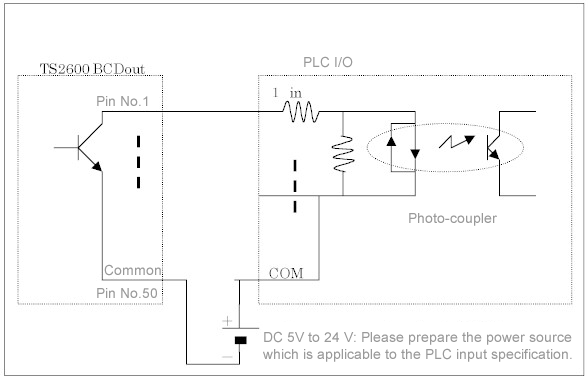
Wiring example is as follows.
BCD out specification
| Applicable plug | DX40-50P (Hirose electric co., ltd.) |
| Applicable plug cover | DX-50-CV1 (Hirose electric co., ltd.) |
| AA8012 BCD cable (5 m, one side open) is provided as an option. | |
| Output type | Open collector, Positive logic |
| Signal name with * mark is outputted with negative logic. |
| IC : 74LS07 | Withstand voltage : 24V max, Sync current : 32mA max, Residual voltage : 0.6V |
| Pin No. | Signal name | Pin No. | Signal name |
|---|---|---|---|
| 1 2 2 4 5 6 7 8 |
Data output (Torque) 1×100 2×100 4×100 8×100 1×101 2×101 4×101 8×101 |
26 27 28 29 30 31 32 33 |
Data output (Rotation) 2×101 4×101 8×101 1×10² 2×10² 4×10² 8×10² 1×10³ |
| 9 10 11 12 13 14 15 16 |
1×10² 2×10² 4×10² 8×10² 1×10³ 2×10³ 4×10³ 8×10³ |
34 35 36 37 38 39 40 41 |
2×10³ 4×10³ 8×10³ NC NC NC NC NC |
| 17 18 19 20 21 22 23 24 15 |
NC NC NC NC Data output (Rotation) 1×100 2×100 4×100 8×100 1×101 |
42 43 44 45 46 47 48 49 50 |
Torque polarity output [-] Torque polarity output [+] NC NC NC Hold input * Busy input * Print command output * Common (0 V) |
Hold input *
During signal input with low level, BCD output data is held.
Busy input *
Used when it is connected to the printer. Input Lo level signal while the printer is connected and activated.
Print command output *
When it receives hold or busy signal input, negative logic signal around 100 to 150 µs of pulse width is outputted.Revised:2000/06/09
