
![]()
![]()
![]()


Logical expressions and truth tables
Logic is a discipline which seeks to clarify and explain matters through coherent, methodical reasoning, one branch of which is algebra (Boolean algebra). Algebra dichotomizes all phenomena as true and false and considers their essential nature through combinations thereof. Phenomena to be characterized as true and false are expressed as variables denoted by terms such as A, B, and C. The values which these variables assume, for example, "true", are expressed as 1, and "false" as 0. Combinations of logical variables are referred to as logical expressions, and three basic functions are used to construct these expressions: logical product (AND operations), logical summing (OR operations), and negation.
You are probably familiar with questions such as whether something operates in AND fashion or OR fashion, and this is an issue of logical expression. Logical variables and their results in 1 and 0 form, arranged in tabular form, are known as a truth table. In the case of a truth table showing logical product, when variables A and B are located in a given area and these elements represent "A as well as (AND) B", these elements are termed the "logical product of A and B."
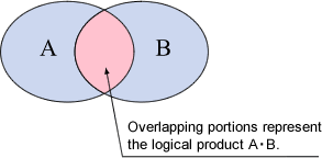
Table 1 Truth table of logical summing
| A | B | A•B |
|---|---|---|
| 1 | 1 | 1 |
| 1 | 0 | 0 |
| 0 | 1 | 0 |
| 0 | 0 | 0 |
Note:
When A and B are true, A•B equals 1, and
other combinations result in 0.
Logical expressions and positive logic/negative logic in digital IC circuits
In digital IC circuits, one signal or signal line is regarded as high level ("H") or low level ("L"), for example, 5V when high, and 0V when low. In other words, the question of whether a single signal (variable) is output of either H or L single level, which allows us to assign corresponding meanings, for example 1 (true) to H and 0 (false) to L. The preceding Table 1, expressed as signal levels in digital IC circuits, results in Table 2 and Table 3.
Table 2 AND circuit truth table (positive logic)
| A | B | A•B |
|---|---|---|
| H | H | H |
| H | L | L |
| L | H | L |
| L | L | L |
Table 3 AND circuit truth table (negative logic)
| A | B | A•B |
|---|---|---|
| L | L | L |
| L | H | H |
| H | L | H |
| H | H | H |
Assignment where H corresponds to 1 (true) and L to 0 (false), as in Table 2, is termed "positive logic"; the reverse, where L corresponds to 1 (true) and H to 0 (false), as in Table 3, is termed "negative logic."
Positive logic, negative logic, and BCD output
Binary coded decimal (BCD) output signals are expressed as 4-signal line combinations of H and L representing the decimal numerals 0-9. In a 4-signal line, each signal is assigned respectively to a place order corresponding, from the lowest place order upward, to 20(=1), 21(=2), 22(=4), and 23(=8) and appears as 4 binary place orders. The series referred to generally as 1,2,4,8 is present here. For example, a numeral represented as 1001 in binary corresponds in decimal to 1×23 + 0×22 + 0×21 + 1×20 = 9. Table 4 presents the truth table of BCD code
Table 4 BCD code (binary-coded decimal) truth table
| Decimal | Binary | Decimal | ||
|---|---|---|---|---|
| 1st place(23) | 1st place (22) | 1st place (21) | 1st place (20) | |
| 0 | 0 | 0 | 0 | 0 |
| 1 | 0 | 0 | 0 | 1 |
| 2 | 0 | 0 | 1 | 0 |
| 3 | 0 | 0 | 1 | 1 |
| 4 | 0 | 1 | 0 | 0 |
| 5 | 0 | 1 | 0 | 1 |
| 6 | 0 | 1 | 1 | 0 |
| 7 | 0 | 1 | 1 | 1 |
| 8 | 1 | 0 | 0 | 0 |
| 9 | 1 | 0 | 0 | 1 |
Note:
Though a binary combination of the numeral 1111 is conceivable, binary coded decimal does not allow for values of 9 or greater, and an error results (values of 9 or greater are sometimes assigned to characters such as A, B…F).
Table 4 represents 1-place order components, but when a 4-place order decimal is represented in BCD, the result displayed is 4 place orders x 4 signals = 16 signals (a 16-signal line).
The catalog specifications for BCD output include description of positive logic and negative logic. When notation is in positive logic, as in the foregoing Section (2), true values assume H (high level, e.g., 5V). The specifications also state that when notation is in negative logic, true values assume L (low level, e.g., 0V) and are output. BCD output circuits also sometimes make use of open collector output circuits. With an open collector, a transistor is used in the final output circuit, and the words "on" and "off" are used based on whether a transistor operates (ON) or does not operate (OFF); on means L, and off means H. Consequently, in signal exchange with an open collector, attention is needed to the positive/negative logic associations of on (L), off (H).
The following table shows 5-place order BCD code and a open collector output, negative logic truth table displayed as on (ON displayed) and off ( -- displayed). Please refer to the table.
Converting BCD output
Disregard decimal places of values displayed in the footer text box, enter in half-width characters, and press the "Convert" button.
The bits output are then displayed in the lower table. To re-input, press the "Reset" button and then input again.
Revised:2009/07/21
