
![]()
![]()
![]()


The TM-3100 series is compatible with the previous
models of the TM-800/TM-8000 series and the TM-2100 series.
Conventionally, we are providing 4 standard function models of the
TM-3110 (display only), TM-3120 (BCD open collector output), TM-3130
(analog output) and the TM-3140 (comparator output). However, when
you wish to make the TM-3100 series compatible with the TM-2120
series (BCD output model), the card needs to be replaced with the
optional TM-0321 BCD output (voltage output) card. (Combination of the
TM-3110 and the TM-0321.)
Although the output current of the BCD output of the TM-800/8000 series and TM-2100 is 4 mA,
in the internal circuit of the voltage output of TM-0321, the open collector output is pulled up to +5 V with a 10 kΩ resistor.
Depending on the amount of impedance of the receiving circuit, correct voltage value may not be output.
Also, when a receiving circuit that current is passed into is used, it may not operate properly depending on the device to be connected.
Please check the specification and operation of the device to be connected before use.
[Additional explanation]
The TM-3100 series has "SS measurement" and the optional "TS-0350 (RS232C/GATE)" as the new functions in addition to the conventional function.
The basic concepts for the TM-3100 series are the following three points.
• Measures the "frequency" of the input signal and displays the results in various measurement items after calculation.
• By simply setting the unit of "measurement item", the results are converted and automatically displayed.
• Two "measurement modes", such as NORMAL (normal continuous measurement) and SS (measurement between start and stop timings), are available.
The overviews of the measurement mode and measurement item are as follows. Please refer to the installation manual for the measurement using the calculation function or the gate of the TM-0350 (RS232C/GATE).
1. Measurement mode (MEAS MODE)
1-1 NORMAL
In the NORMAL mode, measurement is continued with a specified update interval (e.g.: 1 second) and displayed. The NORMAL mode is used for general rotation speed or line speed measurements. This mode is compatible with old models (TM-800/8000 and TM-2100 series) because the measurement method is the same.
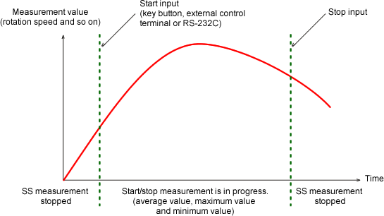
1-2 SS (START/STOP)
The SS mode is used to measure the AVERAGE, MAX (maximum), and MIN (minimum) values in a measurement section. Depending on what condition of the start and stop measurement section is specified, either MANUAL or AUTO measurement is used. In the MANUAL mode, the measurement section is determined by the START and STOP switches (or by the external input of the TM-0350). In the AUTO mode, the measurement section is determined by the start condition and measurement time. The details are provided in later sections.
SS-MANUAL
Select the "MANUAL" mode in the [SS MEASURE MODE]. In the "MANUAL" mode, the average and other values are measured in the interval from the point when the START switch is pressed until the STOP switch is pressed.
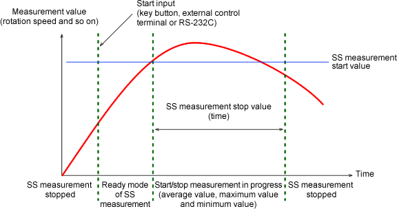
SS-AUTO
Setup the "AUTO" mode in [SS MEASURE MODE]. In the "AUTO" mode, pressing the START switch sets the system in ready state. The measurement starts when the value is reached to the setup start condition and stops when the value is reached to the stop condition. The average value etc. are measured for the interval between the start and stop times.
Example; When the condition is [START: 2000 r/min, STOP: 10 s] setup
If the START switch is pressed at the rotation speed of 1000 r/min, the measurement will start when it reaches 2000 r/min after gradual acceleration. Then, the average, maximum, and minimum values are measured in the passing intervals of 10 seconds. As another example, if the START switch is pressed at the rotation speed of 2500 r/min and the rotation speed is decreased to 2000 r/min, the measurement will be started at this point. Please be careful about the rotation speed when you press the START switch. The measurement value will be displayed on the sub display.
Main display and sub display
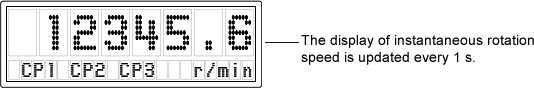
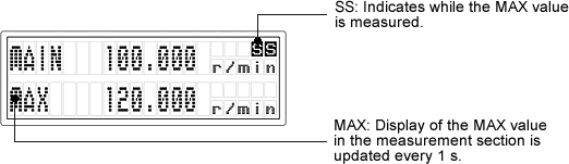
When DISPLAY → 2 LINE is selected in the setup mode, the main display shows the NORMAL measurement value and the sub display shows either the average, maximum, or minimum value of the SS measurement according to the selected value. Examples of the main display in a single line mode and the main/sub display in the two line mode are shown as follows.
TM-3140 (with comparator output), main display (with 1 LINE display)
TM-3110 (display only), main + sub display (with 2 LINE display)
1. Measurement item
The TM-3100 series tachometer measures the period (frequency) of the input signal. Process the calculation by using the measurement frequency with the value which sets at the measurement item as the coefficient value, and display with the specified unit.
The measurement items and the calculation formula are listed in the following table.
| Measurement item | Display unit | Calculation formula |
|---|---|---|
| ROTATION Rotation speed |
r/s, r/min, r/h | ROTATION SPEED=MEASUREMENT FREQUENCY÷PULSE×FACTOR×K |
| L.SPEED Circumferential speed |
mm/s, m/s, mm/min, m/min | L.SPEED=MEASUREMENT FREQUENCY÷PULSE×DIAMETER×π×FACTOR×K |
| VELOCITY Moving speed |
mm/s, m/s, mm/min m/min, km/min mm/h, m/h, km/h | VELOCITY=MEASUREMENT FREQUENCY÷ PULSE DISTANCE×FACTOR×K |
| PERIOD Period |
s, min | PERIOD =1÷MEASUREMENT FREQUENCY×K |
| TIMES Number of times |
1/s, 1/min, 1/h | TIMES=MEASUREMENT FREQUENCY×FACTOR×K |
| FREQ Frequency |
Hz, kHz | FREQUENCY=MEASUREMENT FREQUENCY×FACTOR×K |
| FLOW Flow rate |
ml/s, ml/min, ml/h l/s, l/min, l/h | FLOW=MEASUREMENT FREQUENCY×FACTOR×K |
| P.TIME Passing time |
s, min | P.TIME=PROSESS LENGTH÷L.SPEED ×FACTOR×K (L.SPEED=MEASUREMENT FREQUENCY ÷ PULSE × DIAMETER × π) |
| OTHER Engineering unit |
EU/s, EU/min, EU/h | Engineering unit=MEASUREMENT FREQUENCY×FACTOR×K |
*The example use of the FACTOR: Assume that a decelerator is used and the rotation detector is fixed to the input axis. If it is desired to display the rotation speed of the output axis, setup the gear deceleration ratio as FACTOR. Generally, FACTOR is setup as "1".
2-1 Setup mode (MEASURE)
In the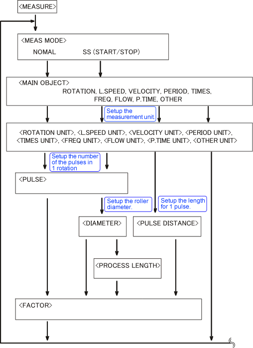
2-2 Setup mode (FUNCTION)
In the
Revised:2009/08/24
