
![]()
![]()
![]()


The setup method to display the speed ○○○.○ m/min after the connection of the TM-2100 and the RP-704ZA-100P/R.
When you setup the TM-2100 series (the TM-2110, the TM-2120, the TM-2130 and the TM-2140), please pull out the body from the case as shown in the following figure 2. Please finish the setup of the TM-2100 series unit before the wiring of the power cable or signal cable.
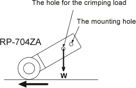
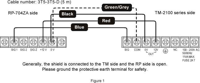
The signal cable connection with the RP-704ZA-100P/R
Connect the cable number: 3T5-3T5-D (5 m) as shown in the following figure 1. When the needs of the long cable which is more than 5 m, available to make it with the specified length.
Setup of the TM-2100 series
Please follow 1 to 4 steps shown in the following figure 2. This is the additional explanation of the meaning of the setup. Please refer to the instruction manual for the details of the function.
If you wish to display the [○○○.○ m/min] with the RP-704ZA-100P/R + the TM-2100 series, setup the unit with multiplier/ index [1.0002×1/10] and the decimal point is [○○○.○].
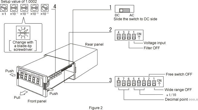
1. AC-DC setup
The signal from the RP-704ZA-100P/R is square wave 12 V in high level, so setup as [DC]. Generally, when the signal is square wave, setup as [DC] and when the signal is sine wave, setup as [AC].
2. Voltage input, filter
Because of the signal from the RP-704ZA-100P/R is a square wave voltage, setup the 4-bit switch of the figure 2 of 2 as [bit 1: OFF (voltage input side)], [bit 2: OFF (no filter)] and [bit 3 and 4: OFF (these are free switches)]. If the signal is open collector, setup switches as [bit 1: ON (contact point input side)] and [bit 2: OFF (no filter)]. If the signal is contact point input, setup a switch as [bit 1: ON (contact point input side)] and to prevent the chattering of the contact point, setup a switch as [bit 2: ON (filter available)].
3. How to calculate the coefficient (multiplier×index)
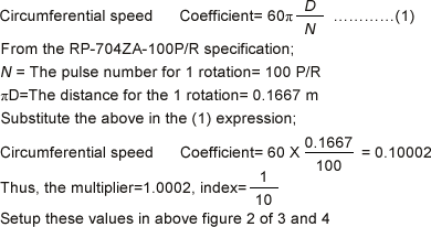
Setup the 8-bit switch of the figure 2 of 3 as [bit 3 and 5: OFF] and [bit 4: ON] (coefficient=1/10). Setup the rotary switch in the figure 2 of 4 as [10002] (multiplier=1.0002).
4. Wide range
Setup the 8- bit switch of the figure 2 of 3 as [bit 1: ON], the frequency range becomes wide and start the measurement from the minimum measurement range of 0.1 Hz (0.01 m/min). During the stop period, it decides 0.1 Hz so you need maximum around 20 s measurement time until the display shows 0. When you setup the switch as [bit 1: OFF], the minimum measurement frequency range becomes 1 Hz (0.1 m/min) or more. During the stop period, you need around 1 s until the display shows 0. Also, setup the switch as [bit 2: OFF] (free switch).Revised:2013/03/16
