
![]()
![]()
![]()


A notice for operating instructions
The main menu of the setup mode
has the following items. (INPUT → MEASURE → FUNCTION
→ DISPLAY → OUTPUT → OTHER)
The flow chart below shows the setting of each item on the menu. Descriptions in red rectangles represent the choices you should make, and the ones in blue rectangles represent the setup values and/or explanations. At the item that does not have a red rectangle, press SET/NEXT switch and go to next. Follow the arrows in the flow chart to perform switch operations. Please refer to "Panel switches and the basic operations" below for the switch operations.
Measurement condition
| Detector | RP-721-120 P/R (the number of output pulse: 120 R/P, Roller diameter: 63.7 mm) |
|---|---|
| Decimal place and display unit | ○○.○○ m/min |
| BCD output | Continuous update output |
| Analog output | 0 to 10V/0 to any value m/min |
| Comparator | User setup |
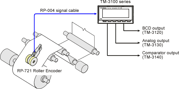
Example of the TM-3100 series rear panel
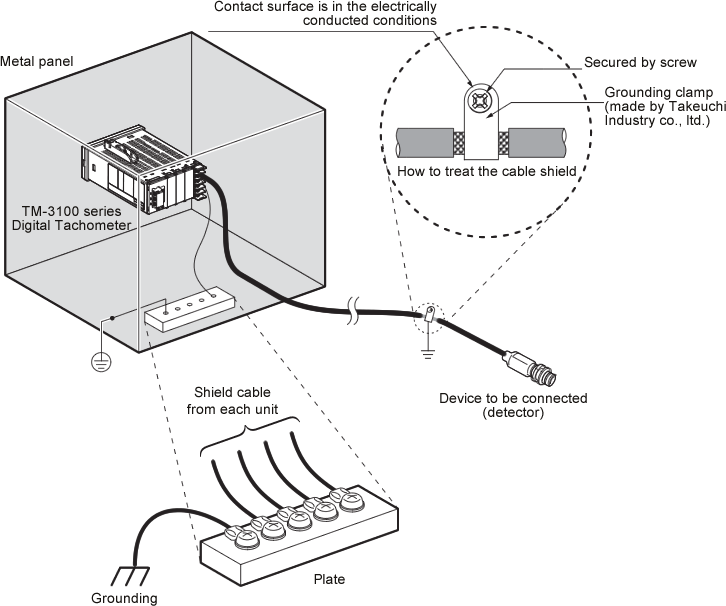
Wiring procedure
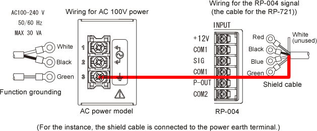
Cautions
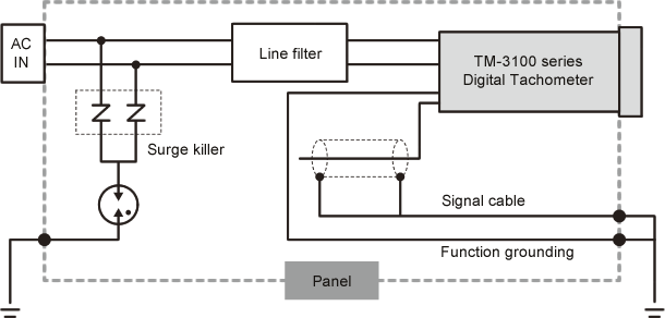
For EMC compatibility, please download the "TM-3100 series installation manual" and follow the instruction. Please store the TM-3100 series into the metal panel, use the line filter and surge killer for power wiring and be sure to use the shielded cable as the signal cable.
The component and wiring diagram for EMC compatibility
Panel switches and the basic operations
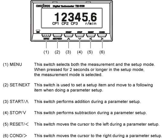
• When you press the MENU switch in the measurement mode, you can go to the setup mode.
• When you press the MENU switch for less than 2 seconds, you can go back to the preceding item.
• When you press and hold the MENU switch, you can go to the measurement mode (where a measured value is displayed) wherever you are.
Setup
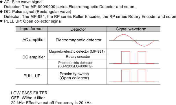
1. INPUT (the input unit setup)
You can setup the installation of the input signal with (INPUT). Setup instruction is as follows.
| INPUT TYPE | DC |
| LOW PASS FILTER | OFF |
After the setup, press <SET/NEXT> button.
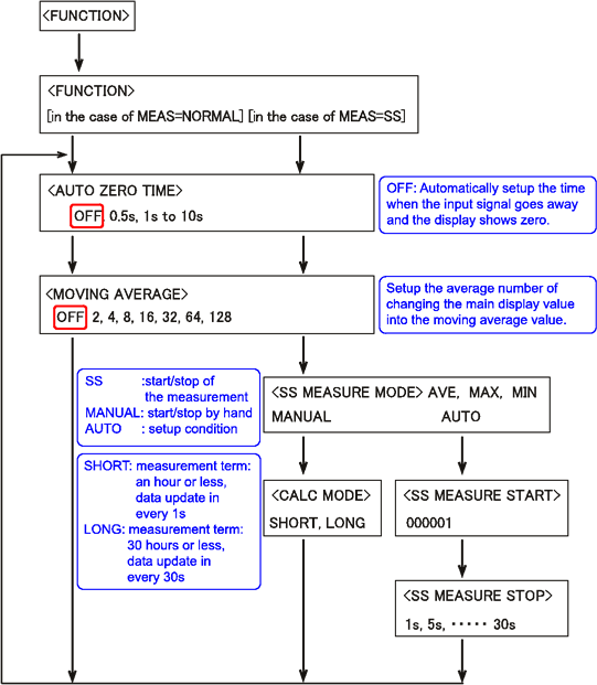
2. MEASURE (the measurement function setup)
You can setup the measurement mode, measurement object and their
conditions with <MEASURE>. The roller diameter is 63.7 mm and
the numbers of the output pulse are 120 P/R for the RP-721-120
P/R. Setup instruction is as follows.
| MEASURE MODE | NORMAL |
|---|---|
| MAIN OBJECT | ROTATION |
| ROTATION UNIT | m/min |
| PULSE | 120 |
| DIAMETER | 63.7mm |
| FACTOR | 1.00000 × 10E+0 |
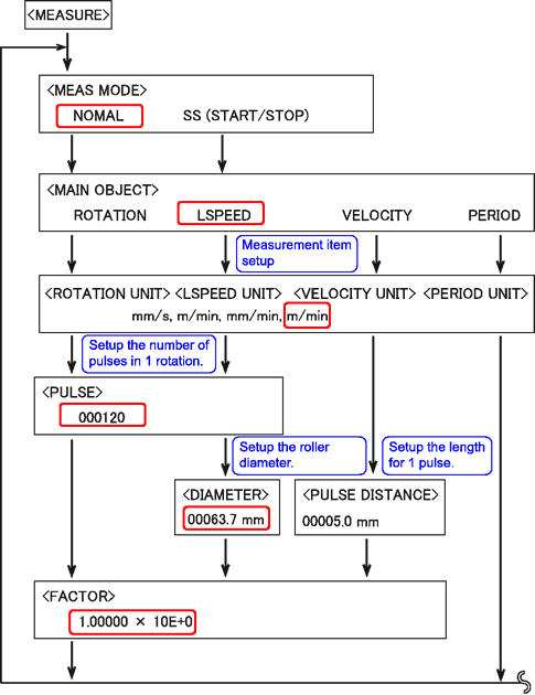
| AUTO ZERO TIME | OFF |
| MOVING AVERAGE | OFF |
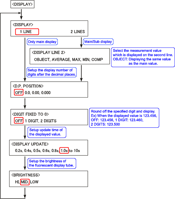
4. DISPLAY (the screen display setup)
You can setup the number of the display digits and display update with. Setup instruction is as follows.
| DISPLAY | 1 LINE |
|---|---|
| D.P. POSITION | ○.○○ |
| DIGIT FIXED TO 0 | OFF |
| DISPLAY UPDATE | 1.0s |
| BRIGHTNESS | MID |
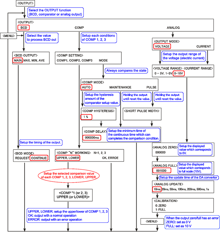
5. OUTPUT (the BCD, COMP or ANALOG output setup)
You can setup the BCD output, comparator output and analog output with
| BCD OUTPUT | MAIN (displayed value) |
|---|---|
| BCD MODE | CONTINUE (continuous update) |
| COMP MODE | UPPER LOWER (setup the selected measurement value of each COMP1, 2, 3. UPPER : measurement value≥selected value LOWER : measurement value<selected value) |
| COMP UPPER (LOWER) | Setup the selected measurement value of each COMP1, 2, 3. |
| ANALOG OUTPUT MODE | VOLTAGE |
| ANALOG VOLTAGE RANGE | 0 to 10 V |
| ANALOG ZERO | 000000 |
| ANALOG FULL | Setup the selected displayed value which corresponds to 10 V. |
| ANALOG UPDATE | 10 ms (If the signal is slow due to the period calculation, the voltage is gradually changes.) |
6. OTHER (saving the panel condition setup)
You can setup the save/readout of the setup condition, the RS-232C and the list of the option with. The setup value is saved in the backup memory, but saved in the COND1 as well just in case.
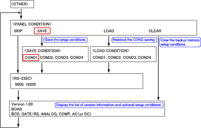
Saving the setup value
Backup memory
The setup conditions of the main menu are saved in the backup memory. The setup conditions in the backup memory are readout automatically after turn the power on.CLEAR
Reset the setup conditions in the backup memory into the initial setting (when shipping).CONDITION
Enable to save the setup condition in the backup memory into the COND1 and readout to the backup memory with LOAD operation.
7. Back to the measurement mode
Press the (MENU) button for a while and back to the measurement screen to start the measurement.Revised:2009/07/21
