![]()
![]()
![]()


Features of the MP-900 series
(1) Non-contact detection enables measurement even of high-speed rotations.
Detection gear
In theory of a rotation detector, detection gears are required to be magnet body and have large magnetic permeability, therefore soft metals (such as S20C, SS41) are generally used. In general, when performing rotating speed measurements, if the gate time (measuring time) is specified at 1 second, using a 60 P/R gear enables direct readout of the rotating speed by the counter.
Number of signals per 1 second (frequency) = rotating speed per 1 minute r/min × 60P/R
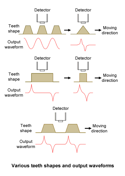
Shape of a detection gear
The figure below shows detector
output waveforms from various types of detection
gears. If the gear is a spur gear, an involute
gear is the most suitable type, and from the
gear with squared-off, triangular or rounded
teeth, the waveforms with high frequency spikes
can be produced. Care is required because spikes
appear in waveforms even when the gear teeth are
chipped in places.
Furthermore, if the gear teeth are magnetized,
please be aware that reciprocal interference
between the teeth and the permanent magnets
inside the detector will result in a reduction
of the output voltage, and abnormal waveform
signals.
Recommend teeth shape of the gear
We recommend an involute gear to obtain the most suitable output voltage. If you make the gear by yourself, please refer to "Recommended gear".
The MP-001 Detection Gear
We provide the MP-001 Detection Gear as an option (sold separately from the detectors).
| Module | 1 |
|---|---|
| Number of gear teeth | 60 |
| Shape of gear | Involute |
The MP-900 series output voltage waveform
As above, when the detector is combined with an involute gear, outputs a sine wave approximation according to the number of gear teeth. Amplitude of the sine wave approximation depends on the conditions as follows.
(1) Mounting gap between the detection gear and the MP-900 series detector
(2) Number of module of the detection gear
(3) Magnetic characteristics of the detection gear
(4) Influence of the magnetism surrounding the detection gear and the MP-900 series detector
(5) Rotating speed (frequency)
(6) Length of the signal cable
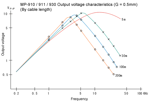
If rotating speed (which is converted to the frequency of output signal) is expressed as X-axis and amplitude is expressed as Y-axis, the graph of typical amplitude characteristic is as below.
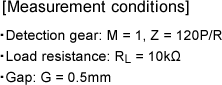
Measurement conditions |
|
 |
 |
|
|
Table of relationship between a detection gear and the MP-900 series
| G: Gap between the detection gear and the detector | The narrower the gap is, the slower rotation speed can be detected. |
|---|---|
| Teeth Shape of the detection gear | Involute |
| Material of the detection gear | Ferromagnet (material with a property of being strongly attracted to a magnet) S20C, SS41, etc. |
| Size of the detection gear | The unit
module (M) is used. This is the value which determines the size
of teeth, and two gears of the same module can engage. Module = Pitch circle diameter / Number of teeth M = 1 or more, tooth width = 4mm or more |
| Cautions for mounting | • Do not
mount two or more the MP-900 series closely. • Do not mount in the ferromagnetic environment such as near a large motor. |
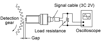
| Signal cable | • Exclusive
signal cable or 3C2V coaxial cable • When the signal cable is 20m or more, we recommend the use of the PA-150 Isolated Amplifier. |
Revised:2006.09.29