![]()
![]()
![]()
Digital Gauge FAQ


The followings are the wiring diagram and the setup procedure of the connection between the GS/BS series Linear Gauge Sensor and the RV-3150 Reversible Counter. Please prepare the instruction manual in your hands.
1. Wiring diagram
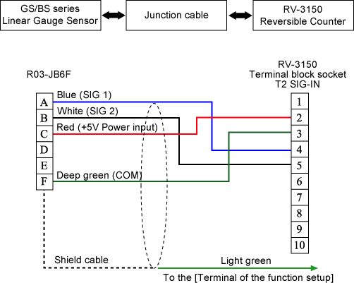
*The junction cable is prepared as an option.
2. Setting sensor input channel (factory default setting: 0 P-IN)SENSOR CH SET |
3. Setting sensor type (factory default setting: 0 DUAL )
The output signal of the GS/BS series are the two-phase wave (voltage) output, please setup as follows with the "SENSOR TYPE SET" of the parameter setup function of the RV-3150.
SENSOR TYPE SET |
4. Setting multiplier (factory default setting: 2 *4)
When you connect the RV-3150 with the GS/BS series, please setup the multiplier number as four as follows with the "PULSE MULTIPLIER SET" of the parameter setup function of the RV-3150.
PULSE MULT SET |
5. Setting counting direction (factory default setting: 0 (+) )
When the timing of the GS/BS series spindle is pushed in set as plus (+) counting, please setup as follows with the "SENSOR DIRECTION SET" of the parameter setup function of the RV-3150.
SENSOR DIR SET |
6. Setting decimal point position (factory default setting: 0 OFF)
When you connect the RV-3150 with the GS/BS series, please setup the decimal point position as follows with the "DICIMAL POINT SET" of the parameter setup function of the RV-3150.
When the resolution is 1 µm
D.POINT SET |
When the resolution is 10 µm
D.POINT SET |
7. Setting analog output full-scale (factory default setting FS→999999)
When you connect the RV-3150 with the GS/BS series, please setup the full-scale value (F.S. value: 10 V) of analog voltage output as follows with the "ANALOG FULL SCALE SET" of the parameter setup function of the RV-3150.
When you want to select the full-scale value as 30 mm (measurement unit: 1 µm)
ANALOG FS SET |
When you want to select the full-scale value as 30 mm (measurement unit: 10 µm)
ANALOG FS SET |
| Output update time | 15 ms or less |
|---|---|
| Resolution | 12 bit D/A method
Stroke 50 mm type, 1 µm unit: 25 µm = 5 mV output |
| Linearity error | ±0.3 %/F.S. |
8. Setting calibration signal output
When you operate the calibration of the output
voltage, please setup as follows. Moreover, when you finished
the calibration, please be sure to restore the setting to 0
(zero).
When you want to output the full-scale value with 10 V
CAL SET |
9. Please refer to the RV-3150 instruction manual to setup the followings when necessary.
• Setting index setup
• Setting comparator condition
• Setting offset value
• Setting LCD upper/lower line display item
• ON/OFF Setting ratio operation function to ON or OFF
• Setting BCD output logic
• Setting RS-232C baud rate
• Setting LCD back light condition
Revised:2001/01/12