![]()
![]()
![]()
Digital Gauge FAQ


The signal output circuit of the GS and the BS series Linear Gauge Sensors are as follows.
Signal output
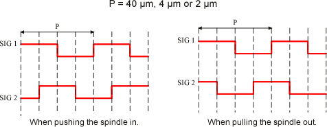
The sensor outputs with the 2-phase pulse signal. The distance of 1 pulse is shown in the following diagram. If you want to read the signal directly with connecting the display unit other than our product, you need to use the multiplication circuit and convert the unit of the sensor into 10 µm or 1 µm. Please pay attention to the noise.
| The minimum display unit for GS and BS sensor | The distance of 1 pulse |
|---|---|
| For the sensor of the unit of 10 µm | 40 µm |
| For the sensor of the unit of 1 µm | 4 µm |
| GS-7000 series | 2 µm |
| GS-3800 series | 0.4 µm |
Output circuit, connector wiring diagram
There are 4 different types of the output circuit depending on the models.
| GS-1713/1730/1813/1830/4713/4730/4813/4830/6713/6730/6813/6830/5050/5100/5051/5101 |
|---|
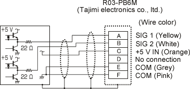 |
| BS-102/102W/112/112W |
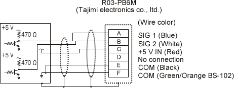 |
| GS-7710A/7710NA |
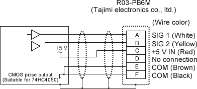 |
| GS-3813/3830 |
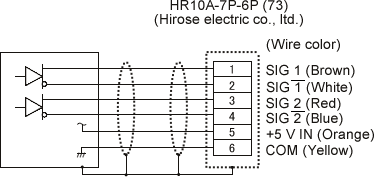 |
 R03-PB6M |
Pin NO. | Signal name | Wire color of the GS series (excluding 7000 and 3800 series) | Wire color of the GS-7000 series | Wire color of the BS series |
|---|---|---|---|---|---|
| A | SIG 1 | Yellow | White | Blue | |
| B | SIG 2 | White | Yellow | White | |
| C | +5 V IN | Orange | Red | Red | |
| D | NC | Unused | Unused | Unused | |
| E | COM | Grey | Brown | Black | |
| F | COM | Pink | Black | Green/Orange (BS-102) |
 |
Pin NO. | Signal name | Wire color of the GS-3800 series |
|---|---|---|---|
| 1 | SIG 1 | Brown | |
| 2 | White | ||
| 3 | SIG 2 | Red | |
| 4 | Blue | ||
| 5 | +5 V IN | Orange | |
| 6 | COM | Yellow |
Revised:2013/05/20