
![]()
![]()
![]()


The DG-4240 Digital Gauge Counter can be used in combination with the gauge sensor to operate the measurement. All of the GS series latest and previous models can be conformed to the counter.
(1) Front panel
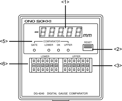
(1) Display
Displays a measurement value using 5-digit numeric with the unit of mm. When a measurement value is negative, "-" is lit on the left side of the display. When a measurement error occurs, the displayed value is flashed. (Please refer to the "Trouble shooting- Flashing of the display" page.)
(2) RESET switch
Resets the displayed value, BCD output and error output after pressing the switch.
(3) UPPER digital switch
Sets the upper limit value for pass-fail decision.
(4) LOWER digital switch
Sets the lower limit value for pass-fail decision.
(5) COMPARATOR indicator
GATE
While the COMPARATOR GATE signal is inputted from <8>
COMPARATOR GATE input terminal (No. 8) or the COMPARATOR GATE
input (Pin 34) of <16> BCD OUT connector on the rear panel, the
switch is lit on in red. While lighting, the pass-fail decision
is forcedly stopped and all decision result output turns OFF.
LOWER
When the measurement value is smaller than the value
specified by (4) LOWER digital switch, the switch is lit on in
red.
OK
When the measurement value is larger than the value
specified by (4) LOWER digital switch and smaller than the value
specified by (3) UPPER digital switch, the switch is lit on in
green
UPPER
When the measurement value exceeds the value specified by
(3) UPPER digital switch, the switch lit on in red.
(2) Rear panel
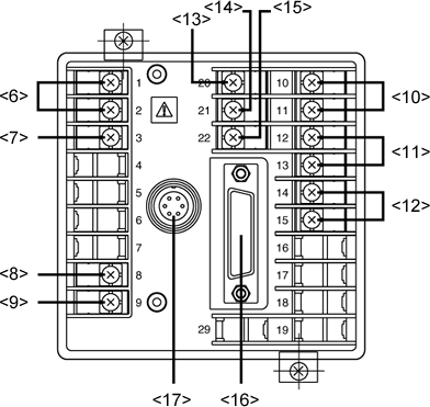
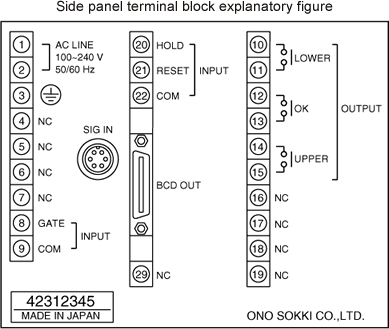
(6) Power input terminal (No. 1, 2)
Inputs power source of 100 V to 240 V AC.
(7) Ground terminal (No.3)
Inputs power source of 100 V to 240 V AC.
(8) COMPARATOR GATE input terminal (No. 8)
When this terminal is short-circuited with <9> COM terminal (No. 9), the pass-fail decision is forcedly stopped and the pass-fail decision result output is turned OFF.
(9) COM terminal (No. 9)
Common terminal for COMPARATOR GATE signal. Turns on when <5> LOWER comparator indicator is lit on with the single make contact output.
(11) OK output relay (No. 12, 13)
Turns ON when <5> OK comparator indicator is lit on with the single make contact output.
(12) UPPER output relay (No. 14, 15)
Turns ON when <5> UPPER comparator indicator is lit on with the single male contact output.
(13) HOLD input terminal (No. 20)
When this terminal is short-circuited with <15> COM terminal (No. 22), the display value and BCD output are held. Please be careful that the pas-fail decision result output is not hold.
(14) RESET input terminal (NO. 21)
RESET signal input terminal. When this terminal is short-circuited with <15> COM terminal (No. 22), the display value, BCD output, error indicator and error output are reset.
(15) COM terminal (NO. 22)
Common terminal for HOLD and RESET signals.
(16) BCD OUT connector
Connector for BCD output, pass-fail decision result output, and external command signal input.
(17) SIG IN connector
Inputs a signal from the GS series gauge sensor.
Revised:2000/12/08
