
![]()
![]()
![]()


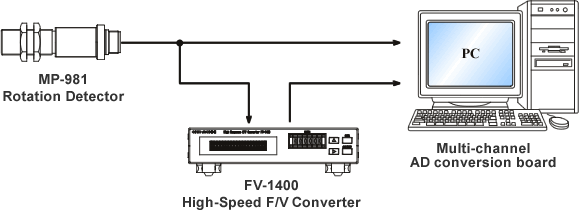
When you connect the input signal and output signal of the FV-1400 to the AD conversion board of a PC, noises from the sample clock of the AD conversion board may be mixed with these signals. Following diagrams are examples of the noise waveforms of the input signal and the output voltage signal.
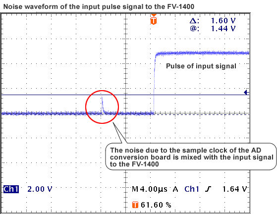
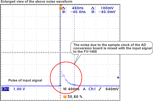
Ex.1
Noise waveforms of the analog signals of the FV-1400
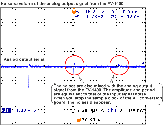
Ex.2
Even though you connect only the output signal from the FV-1400 to the AD conversion board, the noises due to the sample clock may be mixed with the output voltage signal, and moreover may travel to the input signal. In case of setting the input coupling of the FV-1400 to "AC coupling", an accurate measurement may not be performed due to the malfunction caused by the noises mixed with the input signal.
Countermeasures
Please try these countermeasures as follows. In above example cases, the problem was solved by doing both of (1) and (2).
| (1) | If possible, the signal from the sensor should be inputted through an amplifier; that is, use "rectangular wave signal" such as the output signal of the MP-981 Rotation Detector. Moreover, set the input coupling of the FV-1400 to "DC coupling". |
| (2) | Adjust the trigger level of the FV-1400 in order not to pick up the noises. |
| (3) | Inquire the noise countermeasure from the manufacturer of the AD conversion board. |
| (4) | Add a filter circuit (an isolation amplifier, etc.) and transmit the output voltage signal or the input signal of the FV-1400 through it, which prevents the noises due to the sample clock from traveling to the input signal. The filter circuit is to be supplied by our customers. |
Revised:2002.02.15
