
![]()
![]()
![]()
Operating principles of linear gauge sensor
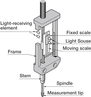
Linear gauge consists of linear gauge sensor (detector) and digital gauge counter (displaying device).
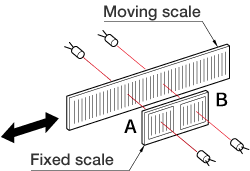
A moving scale which moves together with a spindle is placed opposite to a fixed scale which is fixed in a fixed position in a linear gauge sensor. Dark line is printed in regular intervals on scale so that the scale looks to have light and dark lines. Fixed scale B is located out of fixed scale A by 1/4P (pitch). These moving and fixed scales are sandwiched between light sources (LED) and receiving light elements. (Fig.1)
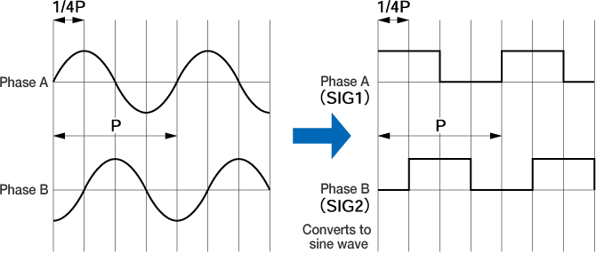
When moving scale moves with respect to a fixed scale, the extent of the light passing through the window in the fixed scale constantly repeats light-dark change. At this time, two synchronized sine-wave signals having a relative 90-degree phase difference are output. A linear gauge sensor judges the direction by this phase lead or delay and then a counter measures an amount of displacement by addition/subtraction operation. (fig.2)
As linear gauge sensor outputs as 1P (pitch) = 4 μm (1 μm resolution type) or 1P (pitch) = 40 μm (10 μm resolution type), multiplying output signal by 4 with digital gauge counter provides output signal as 1/4 of 1P (pitch) of resolution (1 μm or 10 μm).
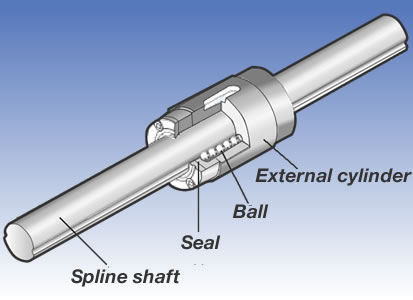
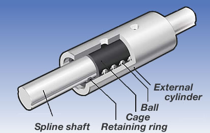
Bearing types used in Linear Gauge Sensors
Bearing used in the Basic type (Linear bushing) - (GS-1713/1730/1813/1830)
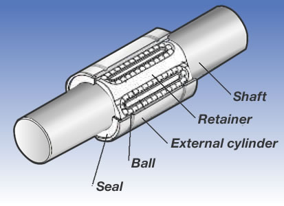
Bearing used in the Long life type & Long stroke type (Endless ball spline)
(GS-4713/4730/4813/4830, GS-5050/5100/5051/5101)
Bearing used in the High resolution type (Finite ball spline) (GS-3813/3830)
Revised:2013/06/03