
![]()
![]()
![]()


For the comparator function, please refer to the "The measurement mode and the comparator function of the VC-2100".
To control the judgment timing of the VC-2100 with the connection of the external device such as PLC, use the AUTO operation by the RESET signal and GATE signal. For farther information, please refer to the operation manual.
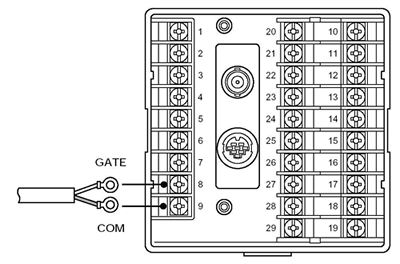
RESET signal, GATE signal input
| Input signal | Rear terminal block No | Specifications | The movement when processing AUTO operation |
|---|---|---|---|
| RESET | No. 7 Reset signal No. 9 COM |
To reset the
operation, short-circuit between terminals or input LOW level signal.
When the voltage signal input condition, it is necessary to keep the LOW level signal condition for 0.1 ms or more. Hi : 4.2 V or more |
(1) GATE OFF (comparator
stops): Reset input
(2) GATE ON (comparator starts) (3) GATE OFF: Read the judgment output (4) Return to (1) and start next measurement |
| GATE | No. 8 GATE signal No. 9 COM |
Input circuit
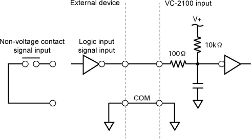
Terminal block

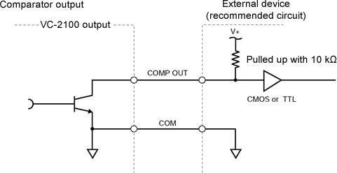
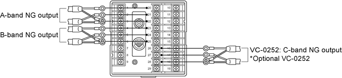
Comparator output (NG signal)
Each of the A-band, B-band or C-band (option) outputs the NG judgment signal.
Band |
Rear output terminal block No |
|
|---|---|---|
| A-band NG output | No.20 NG negative logic
output No.21 NG positive logic output No.22 same as the above COM terminal |
DC 35 V
max、25 mA max Open collector DC 35 V max, 25 mA max (Please refer to the following circuit figure.) |
| B-band NG output | No.23 NG negative logic
output No.24 NG positive logic output No.25 same as the above COM terminal |
|
| C-band NG output (option) |
No.26 NG negative logic
output No.27 NG positive logic output No.28 same as the above COM terminal |
Input circuit
Terminal block
Revised:2002/07/15
