
![]()
![]()
![]()


Set the measurement condition (band-pass filter, etc.) of the A-band and B-band for the vibration level judgment in the same condition, and set the measurement level of the A-band as UPPER level and B-band as LOWER level. From these settings, the NG judgment from both bands are outputted when the measurement value is larger or equal to the setting value. With the combination of the NG outputs of A-band and B-band enables the UPPER, LOWER or OK judgment with the PLC
Measurement judgment timing chart (Example)
The following example shows the judgment when the measurement time is specified by the GATE signal (AUTO) to judge the PEAK HOLD. The NG judgment of the A-band and B-band are selected as "Hi" (measurement value ≥setup value).
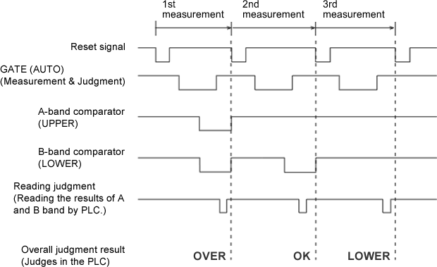
| Judgment | A-band | B-band |
|---|---|---|
| OVER | NG output | NG output |
| OK | (OK output) | NG output |
| LOWER | (OK output) | (OK output) |
Operation procedure
1. Input the reset signal to clear the previous measurement value and judgment result.
2. Start the operation of the test device and when the operation is stabilized, input the measurement time to the GATE signal (AUTO) and start the measurement.
3. Read the comparator outputs (judgment results) of the A-band and B-band after the measurement time is passed (turn off the GATE).
4. Read the comparator results of the A-band and B-band into the PLC to make the overall judgment of UPPER, LOWER or OK.
5. The reset signal and GATE signal (AUTO) are operated when the measurement is in the LOW level (0 V).
6. The comparator outputs of the A-band and B-band are the open-collector outputs (DC 30 V, 25 mA). The negative logic is used in this example.
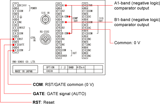
Rear terminal block
The rear terminal block is shown in the following figure. For the signal specification or the wiring procedure, please refer to the instruction manual and perform the wiring correctly.
Measurement mode
sThe VC-2100 has four measurement modes of RMS, PEAK, MAX HOLD and PEAK HOLD. When the band pass filter frequency is set, the measurement is operated with the signal which is already passed the band pass filter. Set the measurement condition of the A-band and B-band separately. When you use the AUTO GATE function, measurement mode is selected as MAX HOLD or PEAK HOLD. For farther information about each measurement mode, please refer to the "The measurement mode and comparator function for the VC-2100"
Setting operation
Operate the trial measurement and select the measurement condition.
Revised:2009.01.19
