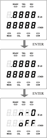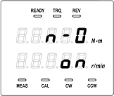

Caution
It is necessary to obtain and enter correction value separately for each CW and CCW. Correction value can be set to each selected direction by the CW/CCW selector switch on the front panel. Check the setting of the rotation direction at first.Obtaining N-0 correction value
1. Set the detection shaft in no-load state (set one side of the shaft in open state) and start to rotate by motor.
2. Change the rotation number in the range of operation and record the torque display value of each number of the rotation.
Use the following table in which the rotation number in the measurement range is described.
| Number of rotations (r/min) | 0 | 1000 | 2000 | 30000 | 4000 | 50000 |
|---|---|---|---|---|---|---|
| Torque count |
| 【Note 1】 | In the torque count column, enter numbers ignoring the decimal point display. Example: For 1.234, enter 1234. For -0.20, enter -20. |
| 【Note 2】 | Torque count refers to the torque display value ignoring the decimal point. |
Up to five points of correction value can be set in the TS-2700. Input points can be approximated with a straight line to perform correction of other than input points. It is also possible to set the interval of the correction value finely where the torque count has large changes to take detailed data, and coarsely where it has small changes.
Example: Rotation number → 200, 500, 1000, 2000 and 5000
3. Input of the N-0 correction value
Caution
Set the correction value in ascending order of rotation. For torque value, input the count value ignoring the decimal point. Torque value which is exceeding the torque capacity cannot be inputted. Up to 99.999 r/min of the rotation can be inputted regardless of the rotation capacity.

Rotation number input at the second point
is enabled.
The operation procedure is same as the input method of
torque correction value of the first point. Description of
the operation procedure is omitted.
Torque correction value input at the third
point is enabled.
The decimal point at the third digit indicating the third
point is lit on.
The operation procedure is same as the input method of
torque correction value of the first point. Description of
the operation procedure is omitted.
Rotation number input at the third point is
enabled.
The operation procedure is same as the input method of
torque correction value of the first point. Description of
the operation procedure is omitted.
Torque correction value input at the forth
point is enabled.
The decimal point at the forth digit indicating the forth
point is lit on.
The operation procedure is same as the input method of
torque correction value of the first point. Description of
the operation procedure is omitted.
Rotation number input at the forth point is
enabled.
The operation procedure is same as the input method of
torque correction value of the first point. Description of
the operation procedure is omitted.

Torque correction value input at the fifth
point is enabled.
The decimal point at the fifth digit indicating the fifth
point is lit on.
The operation procedure is same as the input method of
torque correction value of the first point. Description of
the operation procedure is omitted.
Rotation number input at the fifth point is
enabled.
The operation procedure is same as the input method of
torque correction value of the first point. Description of
the operation procedure is omitted.
When you press the ENTER key after display
of rotation number input at the fifth point, the first
screen of N-0 correction appears.
Enabling the N-0 correction

Revised:2006/05/22