
![]()
![]()
![]()


External switching of the rotation direction is possible by inputting the external control signal using the REMOTE connector on the rear panel. However, the cable length for connecting REMOTE connector has to be 5 m or less, and process shielding if necessary.
(1) REMOTE connector (Rear panel)
| Pin | Signal name | Remarks |
|---|---|---|
| A | CLR IN | Non-voltage contact input (Common is shared.) |
| B | TRG IN | |
| C | CW/CCW Switch | |
| D | COM | |
| E | READY OUT | Non-voltage contact input (Common is not shared.) |
| F | Same as above COM1 | |
| G | TRG OUT | |
| H | Same as above COM2 |
(2) Recommended input signal (Pin A to D)
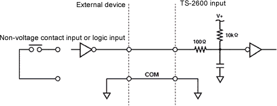
For contact input
| Load voltage | 5 VDC min |
|---|---|
| Load current | 100 mA min |
| ON resistance | 10 Ω max |
| OFF resistance | 500 kΩ min |
| Input Low level voltage | 0 to 1.4 V |
|---|---|
| Input High level voltage | 3 to 5.25 V |
| Input impedance | 1 kΩ |
(3) CW/CCW switching method
Input the following signals between connector pins of C and D (CW/CCW switching).
*It is enabled when the TS-2600 parameter settings of 1 to 3 are ON (EXT).
| Control signal (between C and D) | Function | |
|---|---|---|
| Contact signal | Open | CW |
| Close (short circuit) | CCW | |
| Logic input | Hi level | CW |
| Low level | CCW | |
(Note)
CW/CCW switching of the torque detector is necessary together with
the rotation direction switching of the TS-2600.
Revised:2002/03/15
